IJCRR - 6(5), March, 2014
Pages: 32-42
Print Article
Download XML Download PDF
AN EVALUATION OF THE STRESS DISTRIBUTION IN CORTICAL AND CANCELLOUS BONE AROUND A MICROIMPLANT UNDER VARIOUS LOADING CONDITIONS -AN FESA STUDY
Author: P. Premanand
Category: Healthcare
Abstract:Aim: This study is to evaluate the pattern of stress distribution and bone failure around the Absoanchor micro-implant under various loading conditions and various force levels. Materials and Methods: FESA was originally introduced as a numerical form of analysis in aeronautical engineering and has the potential to obtain a computer generated mathematic model of a real object of complicated shape with its different physical material properties in order to identify the stresses and displacement. Finite element structural models of the Absoanchor implant, cortical bone and cancellous (trabecular) bone of both maxilla and mandible were generated using solid modeling software NASTRAN. In this present study three types of loads were applied on head of implant to simulate different loading conditions. The forces applied were in the range of 25-300gms in both horizontal and diagonal plane, while forces of 10-100gms were applied in vertical plane. Results: There is no bone deformation seen in this study in all the three loading conditions. Conclusion: Since there is no bone deformation for the normal range of force in all the three planes the absoanchor titanium micro-implant placed in maxilla and mandible provide stable anchorage for orthodontic force.
Keywords: Cortical Bone, Cancellous Bone, Absoanchor Microimplant, FESA.
Full Text:
INTRODUCTION
Successful orthodontic treatment has always required intra oral anchorage with a high resistance to displacement. Extra oral traction can be an effective reinforcement but demands exceptional patient co-operation. The size, bulk, cost and invasiveness of prosthetic osseointegrated implants have limited their orthodontic application. Conventional bone screws can be used with bone plates to provide intra oral anchorage, but the screw heads fail to protect the gingiva from the impingement of ligatures or attached elastics and make it difficult to attach coil springs and other orthodontic appliance. Failure of large titanium implants led to the development of micro-implant which is small, affordable, easy to place, routinely resistant to orthodontic forces, can be immediately loaded and easy to remove. One such implant is Absoranchor micro-implant. Current research on implants indicates that bone adaptation to implants is an important factor for successful implant treatment. Incorrect loading or overloading as a result of ineffective implant geometries may lead to implant loss [1, 2] . The Finite element structural analysis (FESA) represents an extension of the matrix method for the analysis of framed and continuum structure. This method is extremely powerful as it helps to accurately analyze structures with complex geometrical properties and loading conditions. The most important step in the Finite element method of structural analysis is to generate, using finite number of discrete elements, a mathematical model which should be as near as possible equivalent to the actual continuum. Such a formulation of a model is referred to as structural idealization or discretization. The continuum is a physical body, a structure or a solid, which needs to be analyzed. The discretization process of continuum is called elements and is connected to the adjacent element only at limited number of points called node [3] . Thus, FESA offers an ideal method of accurate modeling of tooth, periodontium, bone and implant with its complicated three-dimensional geometry representing the in vivo condition similar to clinical situation, thereby permitting the application of various force systems at a point or vice versa and to study the distribution of forces in a qualitative and quantitative form. Thus Finite element Structural analysis (FESA) of the implant can be empirically used for the investigation of maximum anchorage success. The aim of this study is to produce an insight into the influence of an implant system (Absoanchor micro-implant), the direction and magnitude of force application and its stress distribution on the surrounding bone using the Finite element structural (FESA) method.
AIMS AND OBJECTIVES
The aim of the present study was: ? To evaluate the pattern of stress distribution in the cortical and cancellous bone of maxilla and mandible around the microimplant under the following directions of force a) Vertical b) Horizontal c) Diagonal ? To evaluate the pattern of stress distribution in the cortical and cancellous bone of maxilla and mandible around the micro-implant under various force levels. ? To evaluate the amount of bone deformation present around the implant under various loading conditions
MATERIALS AND METHODS
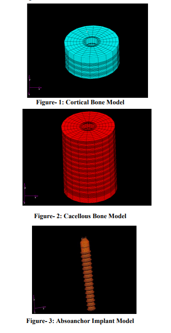
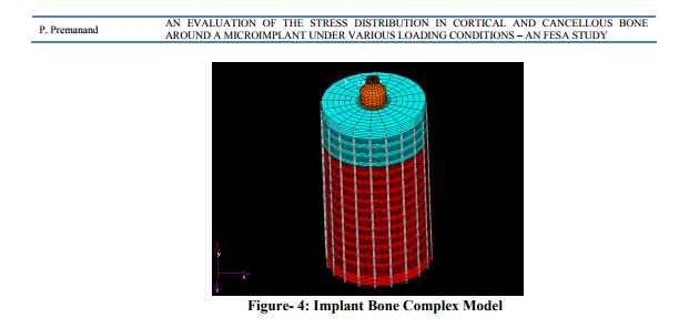
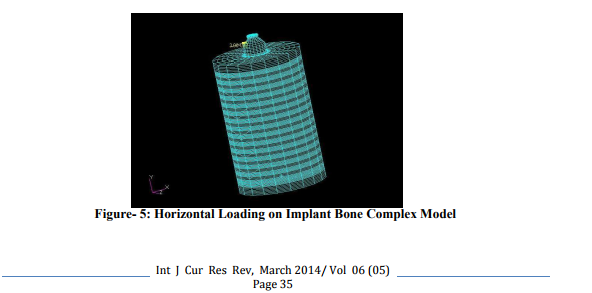
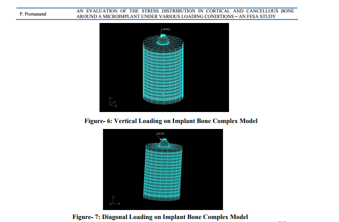
Finite element modeling Finite element structural method offers various advantages including accurate representation of complex geometries, easy model modification and representation of the internal state of stress and other mechanical quantities (Lavernia et al 1981, Huiskes and Chao, 1983)[4,5] . Three Dimensional (3D) CAD Finite element structural models of the implant, cortical and cancellous bones of both maxilla and mandible were generated using solid modeling software NASTRAN. A Finite element structural mesh was used to represent the model of the implant, cortical and cancellous bone. In general, increasingly fine mesh size ensures convergence of a FE solution. Use of large number of elements was especially important in this problem, where stress singularities were expected at the sharp corners [6] . The thickness of the cortical bone in the interdental area between the second premolar and first molar in maxilla and mandible was evaluated with the help of CT scan in a series of patients and was found to be of 2mm thickness in maxilla and 3mm in mandible. The cortical bone was modeled as a cylinder of 2mm thickness for maxilla and 3mm thickness for mandible around the implant with a diameter of 6mm. Cortical bone was generated with 59500 nodes and 59649 elements (Figure-1). The trabecular bone was modeled with a length of 6.5mm and diameter of 6mm for both maxilla and mandible around the implant below the cortical bone model. Trabecular bone was generated with 51309 nodes and 51140 elements (Figure-2). The Absoanchor titanium micro implant [2, 7] with a length of 6mm and diameter of 1.2 mm was modeled, with linear elastic, isotropic and homogenous properties. In the present study Absoanchor implant model was derived from a single mesh pattern that was generated with 20283 nodes and 20360 elements (Figure-3). Implant to bone contact was assumed to be 100% indicating complete osseous integration [8]. Finite element structural models of the implant bone complex (Figure-4) were used to determine stresses and strains in the bone adjacent to the implant surface, under loading. The results were recorded during static loading on the implant.
Material
Properties In the absence of information about the bones precise material properties, assumptions were made according to the majority of studies that used FEM [9]. All materials used in the models were considered to be isotropic, homogenous and linearly elastic [10] . In the cortical bone, Young’s modulus was assumed to be E = 1.37 + 04 N/mm2 and Poisson's ratio = 2.6 - 01 N/mm2 [11] . In the trabecular bone, values were set to E = 1.37 + 03 N/mm2 and Poisson's ratio = 3.0 - 01 N/mm2 [11], and for titanium (implant material) the values were taken to be E = 1.10 + 05 N/mm2 and Poisson's ratio = 3.0 - 01 N/mm2 [11] . Implant loading The force exerted on the head of the implant varies in direction and magnitude. In the present study, 3 types of loads were applied on the head of implant to simulate different loading conditions. a) Horizontal – the load on implant head in horizontal direction was investigated under orthodontic forces ranging from 25gms to 300gms (Figure-5). b) Vertical – the load on implant head in vertical direction was investigated under orthodontic forces ranging from 10gms to 100gms (Figure-6). c) Diagonal - the load on implant head in diagonal direction was investigated under orthodontic forces ranging from 25gms to 300gms (Figure-7).
RESULTS
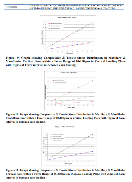
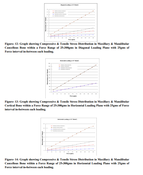
The output results of the Finite Element Structural Analysis are presented in colorful contours. Spectrum of different colour bands on right side of the figure indicates the stress pattern and level of stress distribution in the bone, under various levels of force and direction. (Figure-8) Results were expressed as Principal stresses – Maximum and Minimum. The maximum principal stresses were mostly tensile while the minimum principal stresses were compressive in nature, used on side of force direction [11] . The forces applied were in the range of 25 – 300gms in both horizontal and diagonal while forces of 10 – 100gms were applied in the vertical plane. The stress distribution pattern in maxilla and mandible were assessed for all the three types of force application and the results were graphically represented. (Figure-9-14)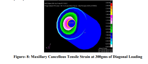
DISCUSSION
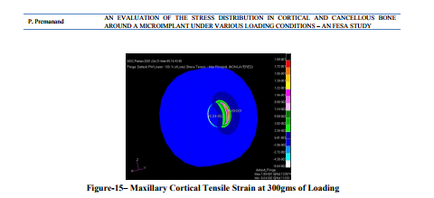
Anchorage control is of great importance in orthodontic treatment. The long term stability of an implant used as an anchorage for orthodontic or orthopedic forces depends on its resistance to displacement forces in all planes [12]. This could be best assessed by observing the stress patterns created around the implant. The present study was aimed at evaluating these stress patterns under various directions of load, which mimics the clinical situation using the Finite element structural analysis (FESA) method. Inappropriate loading causes excessive stress in the bone around the implant and may result in bone resorption. Therefore it is valuable to investigate the stresses / strains in both cortical and cancellous bone. The FESA method is one of the most frequently used methods in stress analysis in both industry and science. It is used for analyzing hip joints, knee prostheses and dental implants [13]. The result of the FESA computation depends on many individual factors, including material properties, boundary condition, and interface definition and also on the overall approach to the model. It is apparent that the presented model was only an approximation of clinical situation. In the present study the force levels of maximum 300gms were used. Since a force of up to 400gms orthodontic force (which is greater than the normal range required for conventional orthodontic tooth movement) has been successfully anchored against an implant anchor in several malocclusions [14, 15] . The results show that all four-stress components in both maxilla and mandible, expressed a linear increase in the stress distribution with an increase in the magnitude of force (Figure-9-14). Stress distribution in cortical bone The stress distribution in the cortical bone was significantly greater than in the cancellous bone (Figure-9, 11and13) as shown in previous studies [8] . Although the present study shows almost identical distribution of the stress in maxillary and mandibular cortical bone under horizontal loading (Figure-13), whereas under diagonal and vertical loading, the stress distribution in the maxillary cortical bone was slightly lesser than that of its mandibular counter parts (Figure-9and11). This could be attributed to the difference in the thickness of cortical bone. Since the cortical bone has much higher elastic modulus than cancellous bone, it is considered the major stress bearing area of the implant [9]; the stresses are more evenly distributed in the mandibular cortical bone than in maxilla. This is further stressed by the work of Miyawaki et al [16] who states that the success rate of implants could be slightly higher than that in the maxilla. This result of this study is in accordance with other studies. [8, 17] The study by Martin et al [18] reported that the ultimate stress of the cortical bone to be higher in compression (170 MPa) than in tension (100 MPa). In the present study the ultimate stress of the cortical bone (1.89 x 10⁻¹ N/mm2 = 0.189MPa) was very much within this limits when a maximum load of 300gms was applied in the horizontal direction (Figure-15), indicating an absence of bone deformation around the implant anchor.
The “strength of materials” [10] principles states that the implant supporting tissue has homogeneous elastic properties, the axial load transmitted from implant to bone concentrates highly in the upper region of bone and decreases rapidly towards the implant base. This phenomenon was observed in that present study showing a rapid decline in the stress distribution from the cortical bone to the cancellous bone. Stress distribution in cancellous bone The results of the present study show that the stress distribution of the maxillary cancellous bone is more than that of the mandibular cancellous bone (Figure-10, 12and14), which is in contrast to the stress distribution found in cortical bone. This could be explained by the fact that owing to reduced thickness of cortical bone of maxilla the significant portion of the load is to be borne by the cancellous bone than that of the mandibular counterpart. This in accordance with the study by Fanuscu et al[8] who demonstrated higher overall stresses in the cortical bone and least overall stresses in the cancellous bone. Comparison of stress distribution under various loading conditions The maximum stress distribution was observed in the horizontal loading condition, which is in accordance with the study by Pierrisnard et al. [19] whereas under the same magnitude of loading, the stress distribution under diagonal loading was significantly lower than that of horizontal loading condition (Figure-13and14). This could be effectively utilized by placing the implant higher up towards the vestibule where by a retractive force from such an implant could be well utilized for both intrusion and retraction of an entire anterior segment, mimicking the power arm design placed on molar anchor tooth. This could also be utilized for efficient use of class II retractive force. Under vertical loading condition a further reduction of stress distribution was noted than the other two loading conditions (Figure-9and10). As only minimal force (10-20 gm) [20] is required for intruding single tooth (for correction of supra erupted molar) or group of teeth (correction of deep bite) the mini implant can effectively serve as a source of anchorage for intruding the above conditions.
CONCLUSION
The pre adjusted edgewise appliance has always been popular because it is easy to work and also provides good control of the tooth during the process of retraction. But anchorage control has always been a trouble to this appliance system, and hence there was always a need to control it. The advent of microimplant enhances orthodontic anchorage without the need for special patient compliance. The result of this three dimensional Finite element structural method shows that - There is no bone deformation seen in this study, in all the three loading condition. - The stress distribution pattern seen in mandibular cortical bone when compared with maxillary cortical bone shows that implant is more stable in the mandible than in maxilla. - Since there is no bone deformation for the normal range of force in all the three planes, the Absoanchor titanium micro implant placed in maxilla and mandible provide stable anchorage to orthodontically intrude hyper erupted unopposed molars, intrusion and retraction of entire anterior segment and can be efficiently used for class II retractive force. In the future modeling the bone as the regenerative tissue, responding to stresses by resorption or regeneration may be a key improvement to the current state of art of FESA models to address the issues found in the study. As developments occur in implant technology, they may have a significant role as anchorage reinforcement aids and make head gear obsolete. However there is a need for high quality research in this area.
ACKNOWLEDGEMENT
Authors acknowledge the immense help received from the scholars whose articles are cited and included in references of this manuscript. The authors are also grateful to authors / editors / publishers of all those articles, journals and books from where the literature for this article has been reviewed and discussed.
References:
1. Alberto R. Mazzocchi and Silvia Bernini. Osseointegrated implants for maximum orthodontic anchroage. JCO 1998 July. 412- 415.
2. Hee-Moon Kyung, Hyo-Sang Park, SeongMin Bae, IL-Bong Kim and Jae-Hyun Sung. Development of orthodontic Micro implants for intra oral anchorage. JCO 2003, vol. 37, No.6: 321-328.
3. Wail N. Al-Rifaie and Ashok K. Govil. Finite element method – for structural Engineers (A Basic Approach).
4. Lavernia C J, Cook S D, Weinstein A M, Klawitter J J 1981 An analysis of stresses in a dental implant system. Journal of Biomechanics 14: 555-560.
5. Huiskes R, Chao E Y 1983 A survey of finite element analysis in orthopedic biomechanics: the first decade. Journal of Biomechanics 16: 385- 409.
6. Dincer Bozkaya, Siman Muftu and Ali Muftu. Evaluation of load transfer characteristics of five different implants in compact bone at different load levels by finite element analysis. J. Prosthet. Dent 2004; 92:523-530.
7. Hee - Moon Kyung, Hyo-Sang Park, and JaeHyun Sung. A simple method of molar uprighting with micro- implant anchorage. JCO – 2002 vol. 36, No. 10, 592-596.
8. Mete. I Fanuscu, Hung V. Vu and Bernard Poncelet. Implant Biomechanics in grafted sinus: A Finite element analysis. J. Oral. Implantology 2004, vol-30, No: 2; 59-68.
9. Cruz et al. Three- Dimensional finite element stress analysis of a cuneiform geometry implant. Int. J. Oral maxillofacial implants 2003; 18: 675-684.
10. Shinichiro Tada, Roxana Stegaroiu, Eriko Kitamura, Osamu Myakawa and Haruka Kusakari. Influence of implant design and bone quality on stress/strain distribution in bone around implants: A Finite element Analysis. Int. J. Oral. Maxillofacial. Implants 2003; 18: 357-368.
11. Monica Vasquez et al. Initial stress differences between sliding and sectional mechanics with the Endosseous implant as anchorage: A 3- Dimensional Finite element analysis. Angle orthod 2001; 71: 247-256.
12. Nilgun- Akin –Nergiz, Ibrahim Nergiz, Axel Schulz, Nejat Arpak and Wilhelm Niedermeier. Reaction of peri-impalnt tissues to continuous loading of osseointegrated implants. AJO 1998; 114: 292-298.
13. Lucie Himmlova, Tatjana Dostalova, Alois Kacovsky and Svatava Konvickova. Influence of implant length and diameter on stress distribution: A finite element analysis. J.Prosthet. Dent. 2004; 91:20-25.
14. Higuchi KW and Slak JM. The use of titanium fixture for Intra oral anchorage to facilitate orthodontic tooth movement. Int. J. Oral Maxillofacial Implants 1991; 69: 401-407.
15. Ismail S.F.H. and A.S. Johal et al. The role of implants in orthodontics. Journal of Orthodontics, 2002, vol. 29, 239-245.
16. Miyawaki et al. Factors associated with the stability of titanium screws placed in the posterior region for orthodontic anchorage. AJO 2003, 124: 373-378.
17. Masumoto T, Hayashi I, Kawamurn A, Tanuku K and Kasai K. Relationship among facial type, buccolingual molar inclination and cortical bone thickness of the mandible. E JO 2001; 23: 15-23.
18. Martin RB et al Skeletal tissue mechanics. Springer 1998; 127-178.
19. Laurent Pierrisnard, Guy Hure, Michel Barquins and Daniel Chappard. Two Dental implants Designed for immediate loading: A Finite Element Analysis. Int J. Oral Maxillofacial. Implants. 2002; 17: 353-362.
20. William R. Proffit et al. Contemporary orthodontics. Third Edition.
|
 IJCRR
IJCRR 


 This work is licensed under a Creative Commons Attribution-NonCommercial 4.0 International License