IJCRR - 10(20), october, 2018
Pages: 20-24
Date of Publication: 26-Oct-2018
Print Article
Download XML Download PDF
Computer Aided Designing/Computer Aided Manufacturing in Dentistry (CAD/ CAM) \- A Review
Author: Sriram S., Vidhya Shankari, Yohan Chacko
Category: Healthcare
Abstract:The Computer Aided Designing Computer Aided Manufacturing (CAD/CAM) technology has become an increasingly popular part of dentistry over the past 25 years(3). The development of CAD/CAM technology in restorative dentistry has evolved drastically(4). By addressing the various dental office issues, digital impressions, with its enormous benefits, along with CAD CAM will make digital intraoral scanning into a routine procedure for most dental restorative procedures in the future. Furthermore, digital impressions reduce the number of visits required for treatment and also increasing effectiveness of the treatment in terms of accuracy and precision. Patients will thereby be benefitted from the comfort and the pleasant experience offered at the dental chair. This makes the restorations fabricated from the lab more consistent, requiring reduced chair time. With the popularization of such a technology, tremendous growth in several areas of dentistry that can potentially benefit from digital impression taking and digital models (restorative dentistry, prosthodontics, orthodontics , dental implantology) in the coming years and witness a true digital revolution in the field of dentistry. This would make treatment planning more efficient with reduced discomfort and increased treatment efficiency. It allows the use of newer high strength materials with excellent biocompatibility combined with, provisions for aesthetic designs, improved precision of fit and longevity. However, these advantages must be balanced with the high initial cost of CAD/CAM systems and the need for additional training. The CAD/CAM systems offer the advantage of automation of fabricating dental restorations with increased quality over a short period of time. The Machinable ceramics are extremely suitable for the fabrication of restorations by CAD/CAM technique as they can be designed and milled in their soft pre-sintered condition and subsequently sintered to improve their physical properties. New high-strength core materials have been developed for all-ceramic restorations. However, most of the systems are limited to replacement of the anterior and premolar teeth, require large connector dimensions and may require the use of more technique - sensitive clinical procedures such as adhesive cementation. The article gives a critical insight on digital impressions and various CAD/CAM technologies available for fabrication of restorations and prosthesis
Keywords: CAD/CAM, scanners, Steroelithography, Milling devices, Optical scanners
Full Text:
INTRODUCTION:
From its inception to now dentistry has covered great milestones in terms of invention and precision to provide us with better working conditions and increased comfort for both dentists and patients(1). The technological changes taking place over the years are truly revolutionizing the way dentistry is practiced and the manner in which dental laboratories are fabricating restorations(2). To add to the list of remarkable advancements is Computer aided design (CAD) and computer aided manufacturing (CAM) technology which allows the dentists to provide better care to the patients(1). The CAD CAM technology has become an increasingly popular part of dentistry over the past 25 years (3). More recently the development of CAD/CAM technology in restorative dentistry has evolved dramatically(4). This technology which is used in both the dental laboratories and the dental office can be applied to inlays, onlays, veneers, crowns, fixed partial dentures, implant abutments, even full mouth restorations and complete dentures. CAD CAM is also being used in orthodontics in the form of invisalign retainers.
CAD/CAM technology was developed to overcome several drawbacks associated with the conventional lost wax techniques. The first was to eliminate shrinkage and expansions associated with wax and models. The second was to eliminate shrinkage and porosities associated with casting procedure. The third was to make restoration of tooth easier, faster, and more accurate in terms of precision and fit. In most cases CAD/CAM technology can used to provide restorations to patients within the same day.
More than 30,000 dentists around the world own scanning and milling machines. Worldwide more than 15 million restorations alone have been completed from its inception till date (2). With further advancements, dental CAD/CAM system have the potential to minimize inaccuracies in conventional technique and thus reducing the hazards of infectious cross- contamination associated with multistage fabrication of indirect restorations
This review article gives a critical insight into the various CAD/CAM technologies which are being used to fabricate highly aesthetic and biocompatible restorations for restorative dentistry
HISTORY:
Computer aided-design and manufacturing (CAD/CAM) evolved from the engineering demands of aerospace and automotive industries. It was more than 2,300 years after Euclid that the first true CAD software, a very innovative system called "Sketchpad" was developed by Ivan Sutherland as part of his thesis at MIT in the early 1960s. Sketchpad was the world's first CAD software to be developed.
Dr. Francois Duret was the first to develop dental CAD/CAM in 1971. He began to fabricate crowns with an optical impression of abutment followed by designing and milling (3). Some of the most important figures in dental CAD/CAM development are Froncois Duret of France, Werner Mormann of Switzerland, Dianne Rekow of the United States and Matts Andersson of Sweeden2. Dr Mormann was the developer of the first commercial CAD/CAM system. He consulted with Dr Marco Brandestini, an electrical engineer, who came up with the idea of using optics to scan the teeth. By 1985 the team had performed the first chair side inlay using a combination of their optical scanner and milling device. They called the device CEREC an acronym for computer assisted ceramic reconstruction. Dr Anderson developed the Procera (now known as Noble Procera, Noble Biocare, and Zurich, Switzerland) method of manufacturing high precision dental crowns in 1983. He was also the first person to use CAD/CAM for composite veneer restorations
EVOLUTION OF CAD/CAM SYSTEMS:
•1971: Duret's experimental research.
• 1979: Heitlinger Rodder's experiment
• 1980: Mormann & Brandestini started developing the CEREC system.
• 1984: Fujita concerned with transferring the manufacturing processes to the
dental care industry.
• 1985: Siemens Dental, today SIRONA, creates the CEREC system
(Germany).
• 1989: CDS Dental (Switzerland) creates DCS Precident and Nobel Biocare
AB creates PROCERA.
• 1990: Creation of Digident (Girrbach Dental GmbH, Pforzheim, Germany)
• 1991: Creation of Celay (Mikrona Technologies, Spreitenbach, CH).
• 1993: Creation of Cicero (Ciceron Dental Systems, Hoorn, NL)
• 1995: Creation of Cercon Smart
• 2001: Creation of Etkon (etkon AG, Gräfelfing, D)
Creation of Everest (KaVo, Leutkirch, Germany),
Creation of Lava (3M ESPE AG, Germany),
Creation of EDC (Wieland Dental, Germany),
Creation of Wol-Ceram (WolDent GmbH, Ludwigshafen, D.)
• 2002: Creation of Bego Meddifacturing (Medical Bego, Bremen)
• 2003: Creation of Perfactory (envisiontec, Gladbeck, D); creation of the
Xawex Dental System (ZrN process, I-Mes, Eiterfield
• 2005: Creation of Dental Designer 3Shape (3Shape A/S, Copenhagen, DK);
Creation of ADG - SW General Subdirector - Software for Automated
Prosthesis Generation, Dental GmbH, Pforzheim, Germany)
•2007- Cadent iTero system
•2008-E4D Dentist system
•2008- Lava chairside oral scanner (COS) ²
CAD/CAM DISCUSSION:
TRIAD AND STAGES OF CAD/CAM FABRICATION
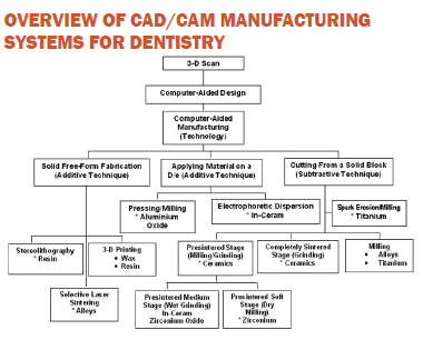
Fabrication of a restoration with CAD/ CAM system has three functional components:
A. Data Capture
B. Restoration design
C. Restoration fabrication
Data acquisition involves making an optical impression of the preparation. It can be done with the help of various intraoral scanning devices such as intraoral camera, mechanical or optical digitizers’ etc.
Restoration designing includes designing the restoration digitally using CAD software. Some of the CAD softwares can design the restoration nearly matching the excellence of restorations produced by master dental technicians.
Restoration fabrication includes milling of the restoration using CAM software with the help of milling machines. Almost all the systems rely on cutting the restoration from a prefabricated block known as subtractive approach. While as an alternative additive CAM approach can also be used in which layering of the material is done to produce a restoration.
COMPUTERIZED SURFACE DIGITIZATION/SCANNING
After cavity preparation, this process involves making an optical impression by surface digitizing or scanning.
3D-surface digitizing or scanning methods are separated into:
Various surface digitization techniques which have been explored are:
The term scanner in dentistry means data collection tools that measure three dimensional jaw and tooth structures and transform them into digital data sets5.
There are two different types of scanners:
• Optical scanners
• Mechanical scanners
a) Optical scanners
The optical scanners works on the principle of collecting three dimensional data by a process called “triangulation procedure”. Here, the light source and the receptor unit are held at a definite angle to one another. The computer uses this relationship to calculate a three dimensional data set from the image on the receptor unit. The light source could be white light projections or a laser beam for illumination. The following are examples of optical scanners on the dental market5:
- Lava Scan ST (3M ESPE, White light)
- Everest Scan (KaVo, White light)
- es1 (etkon, Laser beam).
The recently introduced Nobel Procera scanner uses a newer technology called Conscopic holography technology. Among the various methods the manufacturer describes this technology as superior to triangulation as projected and reflected beams travel the same linear pathway. This allows scanning of steep slopes of up to 85 degrees with ease
b) Mechanical scanner:
In this type of scanner, the master cast is read mechanically by means of a ruby ball and the three-dimensional data is acquired. Currently Procera Scanners Piccolo and Forte (Nobel Biocare) are the only examples for mechanical scanners available in dentistry.
Advantages: Mechanical scanners have a relatively high scanning accuracy and the diameter of the ruby ball is set to the smallest grinder in the milling unit, so that all data collected by the system can be milled.
Disadvantages: The highly complicated mechanics involved in the system, makes the apparatus very expensive and the processing time is more compared to optical scanners(5).
Mechanical digitizers must capture the entire surface of a prepared tooth accurately thereby maintaining the position of the device to the tooth. Many mechanical digitizers are exceptionally sensitive to any motion. Slight movement of patient during data acquisition would compromise the quality of the data, ultimately leading to a restoration that compromise on the fit(6).
In most instances, the scanner used to capture data is an integral part of the CAD/CAM system and operates only in combination with CAD software along with it.
Commercially available scanners:
1. CEREC® – by Sirona Dental System GMBH (DE)
2. iTero – by CADENT LTD (IL)
3. E4D – by D4D TECHNOLOGIES, LLC (US)
4. Lava™C.O.S. – by 3M ESPE (US)
5. IOS Fast Scan – by IOS TECHNOLOGIES, INC. (US)
6. DENSYS 3D – by DENSYS LTD. (IL)
7. DPI-3D – by DIMENSIONAL PHOTONICSINTERNATIONAL, INC. (US)
8. 3D Progress – by MHT (IT) and MHTOptic Research AG (CH)
9. Direct Scan – by HINT - ELS GMBH (DE)
10. Trios – by 3SHAPE A/S (DK)
COMPUTER AIDED DESIGNING
The restorations are designed using Special designated software called CAD software that is provided by the manufacturers for the design of various 3D dental restorations on computer s(5, 7).
The operator enters the data acquired from the scanning process and confirms the features of the preparation. These data are stored in a special format called standard transformation language (STL) data5.
When the designing of the restoration is completed by the software, it is then transformed into virtual model using specific set of commands. Even in the most automated system , the operator has the option to modify the automatically designed restoration to customize it to their requirement. Once the restoration is designed in the CAD, the CAM unit, fabricates the final restoration(8)
COMPUTER AIDED MANUFACTURING
CAM uses the computer generated path to shape a restoration. Earlier systems relied almost on cutting the restoration from a prefabricated block using burs, diamonds or diamond disks.
This approach is termed as “Subtractive method”.
Subtractive fabrication can create complete shapes efficiently and however with large expense of material being wasted.
Processing /milling devices are categorized by means of the number of milling axes:
• 3-axis devices
• 4-axis devices
• 5-axis devices
A) 3-axis milling devices: Three axes milling device has degrees of movement in the three spatial directions. The milling points are defined by the X -, Y -, and Z– values. A milling of subsections, axis divergences and convergences are not possible. This requires a virtual blocking in such
Areas of the milling block. All 3-axismilling devices used in the fabrication of dental restorations can turn the component by 180° in the course of processing the inner and the outer aspect of the restoration. The advantages of 3 axes milling devices are short milling times and simplified control by means of the three axes. Hence, such milling devices are usually less costly compared to those with a higher number of milling axes.
Examples of 3-axis milling devices are: in Lab (Sirona), Lava (3M ESPE), Cercon brain
(Degu Dent).
b) 4-axis milling devices
In four axes milling devices, addition to the three spatial axes, the tension bridge rotationis included as the fourth component. Hence it is possible to adjust long span bridges with a large vertical height displacements and it also facilitates in saving material and milling time compared to three axes milling devices.
Example: Zeno (Wieland-Imes).
c) 5-axis milling devices
With a 5-axis milling device there is, in addition to the four spatial dimensions, rotating the milling spindle is included as 5th axis. This facilitates the milling of complex anatomies with subsections, for example, lower jaw FPDs with converging abutment teeth (end molar tipped towards the medial plane, or also crown and FPD substructures that, as a result of anatomically reduced formation, demonstrate converging areas in the exterior of the framework.
Example in the Laboratory Area: Everest Engine (KaVo).
The quality of the restoration need not necessarily increase with the number of milling axes. The increased number of milling axes provides benefit only in terms of fabricating complex restorations and not relating to the quality of the restoration. The quality of restorations is more from the result of the digitalisation process, data processing and production process than the milling devices. (5).
MILLING VARIANTS
a) Dry processing
Dry processing is used with zirconium oxide blocks with a low degree of pre-sintering. This provides several benefits:
• No moisture absorption by the block, as a result of which there are no initial drying times for the zirconium oxide frame prior to sintering.
• Low investment cost for the milling unit
Disadvantages:
• The lower degree of pre-sintering causes higher shrinkage values for the restoration.
Some manufacturers also offer the option of milling resin material in a dry milling process [Example:Zeno 4030 (Wieland-Imes), Lava Form and Cercon brain].
b) Wet milling
In this type of milling process the diamond or carbide cutter is protected by a spray of cool liquid usually water against overheating of the milled material. This kind of processing is necessary for all metals and glass ceramic material in order to prevent damage to the final restoration through heat development. ‘Wet’ processing is recommended, if zirconium oxide ceramic with a higher degree of pre-sintering is employed for the milling process. A higher degree of pre-sintering results in a reduction of shrinkage and facilitates less sinter distortion.
Examples: Everest (KaVo), Zeno (5, 8).
Selective laser sintering:
Selective laser sintering (SLS) is an additive manufacturing technique used for the low volume production of prototype models and functional components. It starts by converting the CAD data in series of layer. These layers are then transferred to the additive selective laser sintering machine which starts to lay the first layer of powder. As the laser scans the surface, the material gets heated and fuses together. Once the single layer formation is completed, the powder bed is lowered and the subsequent layer of powder is rolled out smooth & subjected to laser. Hence a layer by layer formation of the object takes place (1)
Combination of additive and subtractive CAM approaches: In this initially an enlarged metal die is milled based on the 3D data of the prepared tooth by subtractive approach. Then powder is compacted under pressure on to the metal die, creating an oversized block by means of an additive approach; the block then is milled away to create the contours of the restoration. The oversized restoration is removed from the die and sintered to make the material as dense as possible and to shrink it to its final actual size.
Additive electrophoretic dispersion method: It involves the application of slurry of alumina powder onto the master die to create a coping. The operator then manually trims away the excess material that extends beyond the margin. The outer contour of the restoration is shaped using a subtractive CAM approach. The operator then removes the coping from the die and then infiltrates glass(9).
Additive rapid prototyping technique: It is also known as 3D printing. It is being used to design and print a wax pattern of a restoration (WaxPro printer of the Pro 50 system). It operates similar to an inkjet printer. The machine builds wax patterns of frameworks and full crowns
The wax pattern is then cast or pressed in the same manner similar to conventional waxed restorations. Advanced printing units can be used to print resin type material instead of the wax. This system has wide range of applications than of most CAD/CAM systems for dental restorations; it can be used to fabricate auricular prostheses(8).
Stereolithography
Stereolithography (SLA) is the most commonly used rapid prototyping technology. It is the technique used for creating 3D objects in which a computer controlled laser beam is used to build up the required structure layer by layer (9,10)
CONCLUSION:
In current scenario CAD/CAM technology has become a core part of dentistry with more number of restorations being fabricated. With the advancement taking place digital systems and CAD/ CAM has the potential to replace the conventional technologies. With this restorations can be fabricated quickly, with better properties and esthetic demands of the patient.
ACKNOWLEDGEMENTS:
The authors acknowledge the immense help received from scholars whose articles are cited and included in references of this manuscript. The authors are also grateful to authors/ editors of all those articles, journals, and books where the literature for this article has been reviewed and discussed
CONFLICT OF INTEREST: NIL
References:
1. Takashi M, Yasuhiro H, Jun K, Soichi K. A review of dental CAD/CAM: current status and future perspectives from 20 years of experience. Dental Materials Journal 2009: 28(1): 44-56.
2. Lee C, Alex T. CAD/CAM Dentistry: A new forum for dentist-technician Teamwork. Inside Dentistry, Sep 2006: vol 2, Issue 7.
3. Perng-Ru Liu. Panorama of Dental CAD/CAM Restorative systems. Compendium, July 2005: 26(7): 507-512.
4. Candice Z, Shermian A, Richard M, John D. Rapid prototyping technique for creating a radiation shield. J Prosth Dent, April 2007: 97(4): 236-41.
5. CAD/CAM: Principles, practice and manufacturing management. 2nd edition: Part-I.
6. Duret F, Blouin L. CAD/CAM in Dentistry. JADA 1988: 117: 715-20.
7. Rekow D. Computer aided design and manufacturing in dentistry: A review of the state of the art. J Prosth Dent 1987: 58(4):512-516.
8. Sebastian, Heike, Ralph. Direct mechanical data acquisition of dental impressions for the manufacturing of CAD/CAM restorations. J Dent 2007;35: 903-908.
9. Persson M, Andersson M, Bergman B. The accuracy of a high-precision digitizer for CAD/CAM of crowns. J Prosth Dent 1995; 74:223–9.
10. Persson A, Andersson M, Oden A, Sandborgh-Englund G. A three dimensional evaluation of a laser scanner and a touch-probe scanner. J Prosth Dent 2006;95:194–200.
|
 IJCRR
IJCRR 


 This work is licensed under a Creative Commons Attribution-NonCommercial 4.0 International License