IJCRR - 4(15), August, 2012
Pages: 160-164
Date of Publication: 15-Aug-2012
Print Article
Download XML Download PDF
ENHANCEMENT OF PARAMETERS FOR MULTI LAYER BROADBAND MICROSTRIP PATCH ANTENNA
Author: M. Ajay Babu, I.Govardhani, Habibulla Khan, M.Venkata narayana, Ch. Ravi Teja, P. Rajasekhar Reddy, U.B.V.Surya Rao Dulam
Category: General Sciences
Abstract:In this paper, The proposed model for enhancing gain and return loss, which improves the performance of a conventional microstrip patch antenna. This paper presents a novel wideband probe fed inverted multiple slot microstrip patch antenna. This model adopts contemporary techniques; probe feeding, inverted patch structure and stacked UV-shaped slotted patch. In addition to the easy feeding, the proposed model possesses the advantages of being wide bandwidth, high gain and low return loss. The patch element has the peak gain 13.16 dBi and the return loss is -23.7dB.
Keywords: Broadband antenna; microstrip patch antenna; probe fed; Inverted patch.
Full Text:
INTRODUCTION
Microstrip antennas are the most rapidly developing field in the last few years. Currently these antennas have a large application in mobile radio systems, integrated antennas, satellite navigation receivers, satellite communications, direct broadcast radio, television, etc. The considerable interest in microstrip antennas is due to their advantages compared to conventional microwave antennas as low profile and light weight, easy to fabricate, conformable to mounting structures, and compatible with integrated circuit technology. However, one of the most serious disadvantages of microstrip antennas is limited bandwidth [1]-[3]. To overcome this inherent limitation of narrow impedance bandwidth, low gain and cross-polarization many techniques have been suggested e.g., for probe fed stacked antenna, microstrip patch antennas on electrically thick substrate, slotted patch antenna and stacked shorted patches have been proposed [4]. Recently, there has been considerable interest in the two layer probe fed patch antenna consisting of a driven patch in the bottom and a parasitic patch [5], [6]. By stacking a parasitic patch on a Microstrip patch antenna, the antenna with high gain or wide bandwidth can be realized [7]. These characteristics of stacked microstrip antenna depend on the distance between a fed patch and a parasitic patch. When the distance about 0.1λ mm(wavelength) the stacked microstrip antenna has a wide bandwidth [7], [8]. Recently, aperture-coupled fed stacked patch antenna[9] have been investigated and bandwidths up to 69% have been reported, however, the major drawbacks are the level of back radiation due to use of a resonant aperture and the surface wave excitation. Other feeding techniques such as the use of L-shaped or F-shaped probes have also been proposed yielding to wide impedance bandwidths [10],[11], at the expense of increased complexity of the design and fabrication, especially of the probe. In [10], an Lprobe fed stacked U-Slot patch antenna was proposed with a bandwidth up to 44.4% being achieved. Vslotted rectangular microstrip antenna with a stacked patch has been shown able to achieve bandwidths as high as 47% [12]. This paper proposes UV-shape slotted multiple stacked patch antenna with wide bandwidth, low return loss and high gain characteristics operating between 16.35-17.1 GHz. This employs contemporary techniques namely, the probe feeding, inverted patch, and stacked patch techniques to meet the design requirement.
ANTENNA MODEL
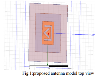
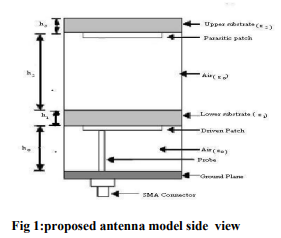
The geometry of the proposed antenna structure is shown in Fig. 1. The antenna is made-up of two UV-shaped stacked patches, two air layers, two Rogers substrates, and a vertical probe connected to the driven patch. The driven and parasitic patches supported by a low dielectric substrate with dielectric permittivity, ε1 and thickness, h1. The parasitic patch is stacked at the height h2 above the lower substrate with permittivity ε2 and thickness h3. Two air-filled layers are used in between the lower substrate and ground plane with permittivity, ε0 and thickness, h0 and in between lower and upper substrates with permittivity, ε0 and thickness, h2 respectively. The proposed two UV-shaped stacked patches are on two different radiating elements. The use of probe feeding technique, stacked multiple slotted patch with thick air filled substrates provide the gain enhancement. The UV-shaped slots for driven patch and parasitic patch are shown in Fig. 1(a). The driven patch is fed by a direct connected probe along the centreline (x-axis) of the patch as shown in Fig. 1(b). Geometry of the antenna:
RESULTS
The resonant properties of the proposed antenna have been predicted and optimized using a frequency domain three dimensional full wave electromagnetic field solver (Ansoft HFSS).
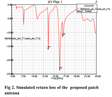
The above figure shows the return loss graph for the proposed antenna. It can be seen that the minimum value is obtained at 16.35 GHz and the minimum value obtained is -23.7 dB. Hence the antenna works well
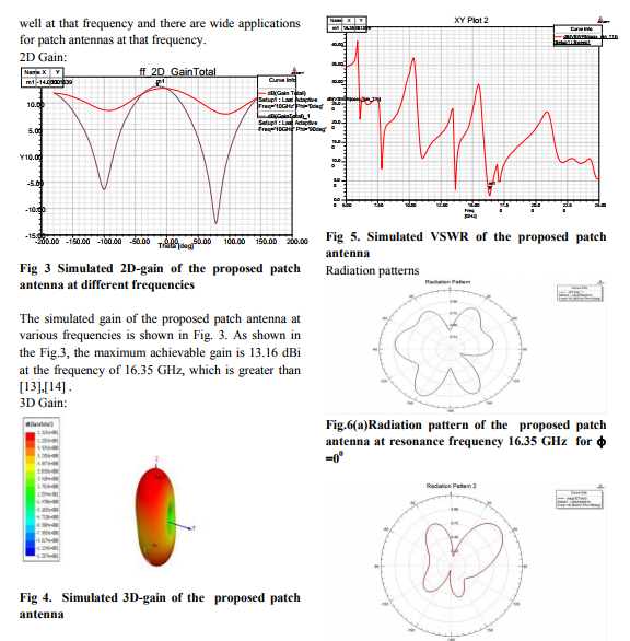
Fig 6(b). Radiation pattern of the proposed patch antenna at resonance frequency 16.35 GHz for ? =900
The above figure shows radiation pattern. As shown in fig.6 the designed antenna displays good broadside radiation patterns for both resonance frequencies when ?=00 and ?=900 . It can be seen that 3-dB beam widths of 580 and 600 are at resonance frequencies of 16.35 GHz and 17.1 GHz.

???????CONCLUSION AND DISCUSSION
A UV-shaped slotted patch antenna has been designed for high gain and low return loss. A newly technique for enhancing gain and low return loss of microstrip patch antenna is successfully designed in this research. Simulation results of a wideband microstrip patch antenna covering 16.35 to 17.1 GHz frequency have been presented. Techniques for microstrip broadbanding, gain enhancement and low return loss are applied with significant improvement in the design by employing proposed slotted patch shaped design, inverted patch and probe feeding. The proposed microstrip patch antenna achieves a bandwidth of 16.35 to 17.1 GHz at -23 dB return loss and the maximum achievable gain of the antenna is 13.16 dBi. The design has demonstrated that stacked patch with UV-shape slots and probe fed can be used to form an antenna with very low return loss further more due to its high gain and broad bandwidth more applications can be anticipated.
ACKNOWLEDGMENT
The authors like to express their thanks to the department of ECE and the management of K L University for their support and encouragement.
References:
1. Y. X. Guo , K. W. Khoo, and L. C. Ongs, ?Wireless circularly polarized patch antenna using broadband baluns?, IEEE Trans. Antennas propag., vol. 56, no. 2, pp. 319-326, Feb.2008.
2. S. J. Lin and J. S. Row, ?Broadband enhancement for dual-freq microstrip antenna with conical radiation?, electron. Lett., vol. 44,no. 1, pp. 515-517, Jan.2008.
3. M. T. Islam, N. Misran, M. S. Islam, M. F. A. Rahim and M. N. Shakib, ?High gain microstrip patch antenna using multiple slot?, in the 4th Int. Colloq on signal processing and its applications (CSPA 2008), Kuala Lumpur, Malaysia, 2008, pp. 421-424.
4. D. Sanchez-Herndez and L. D. Robertson, ? A survey of broadband microstrip patch antennas?, Microwave Journal, pp.60-84, Sep.1996.
5. H. Legay and L. Shafai, ? New stacked microstrip antenna with large bandwidth and high gain?, IEEE proc. Microw. Antennas propag., vol.141,no.3, pp. 199-204, June.1994.
6. W. Y. Tam, A. K. Y. Lai and K. M. Luk, ? Cylindrical rectangular microstrip antennas with coplanar parasitic patches?, IEEE proc. Microw. Antennas propag.,vol. 142, no. 4, pp. 300-306, Aug.1995.
7. S. Egashire and E. Nishiyama, ?Stacked microstrip antenna with wide bandwidth and high gain?, IEEE trans. Antennas propag., vol. 44, pp. 1533-1534,Nov.1996.
8. K. Araki, H. Ueda and M. Takahashi, ? Numerical analysis of circular disk microstrip antenna with parasitic elements?, IEEE trans. Antennas propag., vol. 34, no. 12, pp. 1390- 1394,Dec.1986.
9. S. D. Targonski, R. J. B. Waterhouse, and D. M. Pozar ,?Design of wideband aperture stacked patch microstrip antennas?, IEEE trans. Antennas propag. Vol. 46, no. 9, pp. 1245-1251, Sep.1988.
10. B. L. Ooi and C. L. Lee , ? Broadband air-filled stacked U-slot patch antenna?, electon Lett.,vol. 35, no. 7, pp. 515-517, Apr.1999.
11. B. L. Ooi, C. L. Lee, P. S. Kooi and S. T. Chew, ?A novel F-probe fed broadband patch antenna?, in IEEE Int. Symp. Antennas propag. Soc., vol. 4, pp. 474-477, July.2001
12. G. Z. Rafi and L. Shafai, ? V-slotted rectangular microstrip antenna with a stacked patch?, IEEE Int. Symp. Antennas propag. Soc, vol. 2, pp. 264-267, 2003.
13. K. J. NG, A. A.R. Zainol and M. Tariqul Islam, ? Broadband inverted E-shaped rectangular microstrip patch antenna for 3G applications?, in IEEE National Symp. Microelectronics, NSM 2003, pp.286-289.
14. M.T.Islam,N.Misran,M.N.shakib,B.Yatim,?Low cross-polarization Broadband Microstrip patch antenna?,IEEE Proc. 26-27 Aug 2008.
|
 IJCRR
IJCRR 


 This work is licensed under a Creative Commons Attribution-NonCommercial 4.0 International License