IJCRR - 4(15), August, 2012
Pages: 82-92
Date of Publication: 15-Aug-2012
Print Article
Download XML Download PDF
TAPER QUALITY EVALUATION OF A LASER LATHED STEEL ROD USING MODIFIED FLATBED CO2 LASER CUTTING MACHINE
Author: S.R. Subramonian, A.Z Khalim, R. Izamshah, M. Amran, Hussein N. I. S, M. Hadzley
Category: General Sciences
Abstract:CO2 flatbed laser cutting machine is one of the advanced machining processes which is capable of machining various materials especially super hard engineered materials. The available CO2 flatbed laser cutting machine is only able to flat worksheets. This paper presents the laser lathing quality, particularly taper of cylindrical steel rod using 2D flatbed CO2 laser cutting machine. A specially designed spinning device mechanism was developed to clamp and spin a steel rod of 10 mm diameter. Three significant cutting parameters were controlled in this experiment, namely; cutting speed, spinning speed and depth of cut. The experiments were carried out based on full factorial DOE matrix design. The results show that, laser lathing is capable of improving almost 80-90 percent as compared to manual lathing within the same range of workpiece properties and dimensional accuracy
Keywords: 2D flatbed laser cutting, laser turning, laser cutting, CO2 laser machining, Taper quality
Full Text:
INTRODUCTION
Lasers are widely used in industries as cutting tools as they pose ultra-flexibility in cutting technology in obtaining high quality end product besides being quick set-up, non-mechanical contact mechanics, and small region of the heat affected zone. The transformation from 2D flatbed to 3D laser turning has widely provided the lathing possibilities on them. Based on modification of flatbed lasers, some of the common problems handled with traditional mechanical lathe can be solved, especially lathing of micro dimensional parts. Besides that, the machining tolerances of mechanical lathe also affect the quality of end product. A nonmechanical contact of laser has proved its capability in machining of micro parts, where it reduces the unintentional taper for straight turning. The unintentional taper exist when the cutting force tends to deflect the workpiece, particularly products with big diameter to length ratio. Thus, in order to avoid a large taper variation, laser lathing is found to be very suitable for the machining of cylindrical parts as compared to traditional mechanical lathing. Thus, the dimensional accuracies can be maintained while reducing the residue.
REVIEW OF PREVIOUS WORK
A three-dimensional laser machining concept was developed and investigated kinematically in applications of gear making, threading, turning, and milling in completing a die set [1]. A new 'machine tool' for advanced material processing conceptualizing two converging laser beams was introduced to build optical system around a beam splitter that generates two beams from the same laser head [2]. The new concept of laser machining using two intersecting beams was optimized to investigate the phenomena involved in laser 'blind' cutting [3]. Three dimensional laser concepts were focused mainly in laser machining and laser welding by incorporating one or two laser beams simultaneously at industrial level along with their advantages and limitations [4]. A method of removing stock using two laser beams has been investigated where, the first laser beam produced first kerf and second laser beams intersects with the first beam axis to produce second kerf [5]. Threedimensional (3D) laser machining was done using two laser beams to improve the material removal rate and energy efficiency of laser machining [6]. The important issue in three-dimensional laser shaping is improving the dimensional accuracy along the optical axis without decreasing the materials removing rate. The concept of performing threedimensional laser shaping has been performed using Nd-Yag by [7]. CO2 laser machining of three-dimensional autobody panel was investigated to evaluate the cut quality with respect to kerf width, surface roughness, and heat affected zone (HAZ) [8]. Laser machining of 3D micro part based on layer by layer pealing concept carried out by controlling three main parameters namely power, repetition rate and speed of laser process [9]. Threedimensional laser machining allows implementation of turning, milling, and threading, and grooving were investigated where, issues of material removal rate, surface quality, and process control of laser was discussed [10]. A new approach of 3D laser cutting by 2 kW laser mounted directly to the arm of the robot was studied. This set-up enables a simple, off the shelf solution without having to have complicated beam delivery system for applications that require laser power levels of 2 kW [11]. A fully automated 3D laser micromachining based on the main concept of geometrical flexibility integrating two UV laser sources, excimer and diode pumped solid state laser (DPSS) in ns pulse regime with six degrees of freedom to machine complex parts [12]. Three-dimensional laser machining has been carried out on composite materials using two intersecting laser beams to create grooves on a workpiece where, the volume of material is removed when the two grooves converge [13]. The relationship of processes parameters of pulsed Nd:YAG laser-turning operation for production of micro-groove on cylindrical workpiece was investigated by considering air pressure, lamp current, pulse frequency, pulsed width and cutting speed as correspondence controllable parameters [14]. A novel ultra-short pulse laser lathe system for bulk micromachining of axisymmetric features with three-dimensional cylindrical geometry was studied. One hundred twenty femtosecond pulses from 800-nm Ti:sapphire laser were utilized to machine hexanitrostilbene (HNS) rods into diameters of less than 200 micrometres and the results indicate that surface roughness is dependent upon rotation speed and feed rate [15]. Aninnovative technique of CO2 laser machining to create 3D cavities of a mould was conducted. The removal of a single layer is achieved using multiple overlapping straight grooves where the groove profile has been predicted by theoretical models before the work was carried out [16]. The ablation using femtosecond needs more concentration for micromachining as the advantages of efficient ultra-thin layer peeling without undesirable thermal effects for both opaque and transparent materials. The femtosecond laser turning is highly recommended for excellent surface finish requirements. [17]. The integration of interference phenomenon into femtosecond laser micromachining of circular interference pattern was demonstrated by overlapping infrared femtosecond laser pulses [18]. A square micro-groove on cylindrical surface was performed based on five level central composite design techniques by feedforward artificial neural network (ANN) in process modeling of laser turning [19]. The process features of three-dimensional laser machining was presented with industrial robots, specifying the principal reasons for using lasers and describing the system components with respective practical applications [20]. The characteristics of laser beam including cutting obliquity and cutting direction on 3D laser cutting quality was critically investigated. In this experiment, the range of upward 3D cutting was slightly wider than 2D, and the range of downward 3D cutting was sharply narrower than 2D cutting [21]. The effects of processing parameters on laser cutting of aluminum– copper alloys using off-axial supersonic nozzles are present and a quantitative experimental study is used to determine the influence of processing parameters on the cutting speed and quality characteristic [22]. The relationship between cut edge quality and cut edge roughness to the process parameters was studied in order to find out the optimal cutting conditions. Mathematical models were used in determine the relationship between the process parameters and the edge quality parameters [23].
Experimental Set-Up
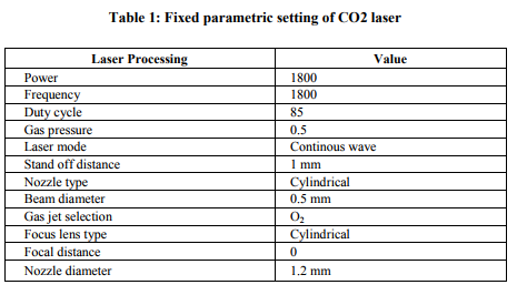
The intention of this research work is to transform 2D flatbed CO2 laser cutting machine into 3D operational capability. To transform 2D cutting into 3D, a work spinner of single phase motor was embedded with a three jaw chuck to hold the circular workpiece. The motor was mounted on the table where, only the laser head will be maneuvered along the center axis of the part by off-setting the table movement control to adjust the depth of cut value for each pass/cut. The motor and chuck assembly was aligned almost perfect vertically and horizontally to prevent collision between laser head and workpiece during lathing process. Besides setting the alignments to prevent geometrical errors and stock accidents, setting of process parameters also play crucial role in obtaining reasonable output quality. The parameters were clustered into three categories; constant parameters, controllable machine parameters and controllable motor parameters. Motor speeds were varied between 1000 and 1500 rpm throughout the experimentation. Table 1 shows the constant parameters used in this experiment.
EXPERIMENTATION AND RESULT
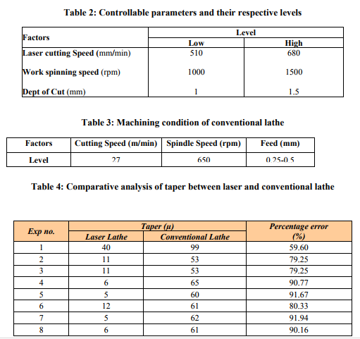
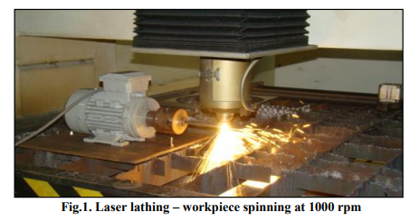
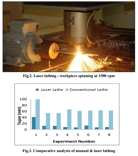
a) Laser Lathing Experiments were conducted by varying the significant parameters as in table of design matrix. Table 2 shows the controllable parameters and actual coded values used for these entire experiments. Figure 1 clearly shows how a motor is placed on the sacrificial table with the workpiece clamped by a chuck and being lathed by the moving laser head. Thus, the non-contact cutting mechanism is taken advantage to perform lathing. For the first cutting, the rotation of workpiece rod was set to 1000 rpm with 680 mm/min laser speed. The observation shows that the obtained lathed surface was rough and requires fine tuning of interaction between laser speed and work spinning. As to further investigate, the next lathing was carried out at 1500 rpm with the laser head speed of 510 mm/min. Figure 2 shows the cutting phenomenon of the latter set cutting condition. The observed results between first and second set of cutting was totally different where, the surface finish of higher spinning speed with reduced laser cutting speed shows better results as compared to earlier.
b) Conventional lathe
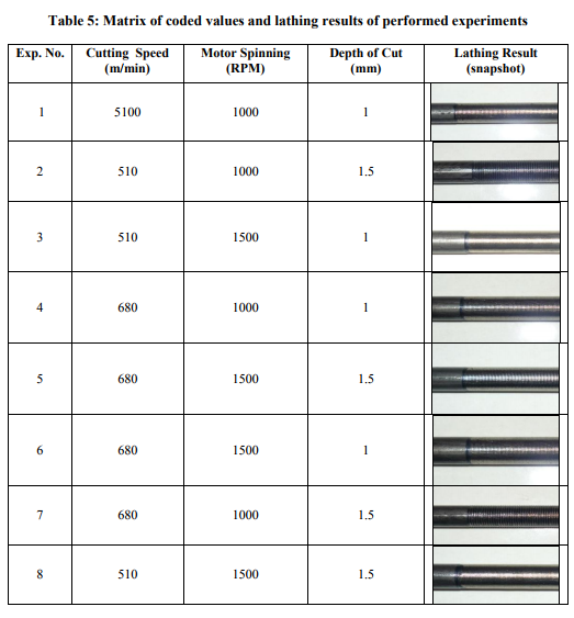
To compare of mechanical lathing with laser lathing, same raw materials were also performed by traditional mechanical lathes. This is to compare the other benefits of traditional lathes (if any) on working with circular stocks. Table 3 shows the machining conditions set on mechanical lathes for rough cut which was obtained from machining handbook [24]. The experimental results of both the manual lathe and laser lathe were obtained successfully. They were compared in terms of percentage for the quality evaluation of roundness. The comparative values of both the lathing techniques are presented in Table 4. Based on the observation, there are large gap of taper between laser lathe and conventional lathe. The overall mean of percentage error between laser lathe and conventional lathe is about 82.9 percent. This error proves that a contact cutting tool (conventional lathe) gives greater impact compared to a non-contact cutting tool (laser lathe). Table 5 shows the matrix of coded values and the lathing results of eight performed experiments. Figure 3 shows the comparative analysis of the manual and laser lathing. It is clear that laser lathing has produced better taper values as compared to manual lathing. Thus, it is confirm that, laser lathing can be performed by flatbed laser cutting machine if the workpiece can be made into rotational towards laser axis.
Taper Quality Evaluation
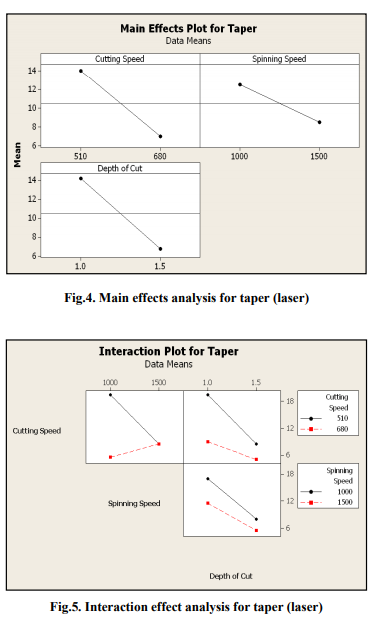
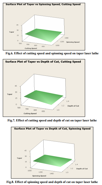
From the main effects plot of laser lathe in Figure 4, the cutting speed, spinning speed and depth of cut shows a significant effect on taper. As per the main effects are concerned, the optimal conditions for best attained taper value, the laser cutting speed, spinning speed and depth of cut should be set at high level with (680 mm/min), (1500 rpm) and (1.5 mm). Figure 5 show that, all the factors have significant interaction, it's means each of factors have correlation between each other. The effect on taper by machining parameters during laser lathe has been analyzed and can be witnessed that taper is very much not affected by depth of cut. The observation found that, increasing the depth of cut does not affect taper value. This was suspected because laser is a noncontact machining. The taper will be increase when the cutting speed and spinning speed decrease. Figure 6 shows the surface plot for taper over the controllable parameters of laser cutting speed and work spinning speed. The observation found that, the high level of cutting speed and lower level of spinning speed provides better quality of taper. Figure 7 shows the effect of cutting speed and depth of cut on taper value of the lathed part. The surface plot shows that, the taper decrease when the cutting speeds and depth of cut increase. The taper tends to increase when the cutting speed and depth of cut decrease. The surface plot effect between spinning speed and depth of cut in Figure 8 shows that, increasing the spinning speed and the depth of cut results in best quality of taper value. The taper remains increase when the spinning speed and depth of cut decrease.
CONCLUSION
Based on the research work carried out, the two dimensional (2D) flatbed laser cutting machine was able to be transformed to perform laser lathing of a cylindrical part. Not only this, comparative analysis of taper quality between the parts lathed using conventional and modified laser machine shows significant improvement up to 90% adopting the latter. This research proved that, super hard work materials which requires investment in obtaining superior cutting tools can now be seen to have cheaper alternate solution without having to have a real expensive 3D laser cutting machine. Thus, the wider range of metallic steel rods are to be lathed using modified setup to investigate suitability of developed system and their respective parametric setting.
ACKNOWLEDGEMENT
Authors are very thankful to the Ministry of Higher Education for funding this project via Fundamental Research Grant Scheme (FRGS/2010/FKP/TK02/3- F0084). Nevertheless, the authors are indebted to thank top level management of UTeM and Faculty of Manufacturing Engineering (FKP) for their continuous support and encouragement. The authors would also render their sincere thanks to LVD Laser technical support personnel Mr. Vegiayan Ramiah for his expertise and advice provided in transforming 2D machine into 3D laser lathing capability.
References:
1. Chryssolouris, G., Anastasia, N., Sheng, P. Three-dimensional laser machining for flexible manufacturing, American Society of Mechanical Engineers, 1991; 50: pp. 163-178.
2. Chryssolouris, G.; Bredt, J.; Kordas, S. Laser Turning For Difficult To Machine Materials. American Society of Mechanical Engineers, 1985; 17: pp. 9-17.
3. Chryssolouris, G., Bredt, J., Kordas, S., Wilson, E. Theoretical aspects of a laser machine tool, Journal of engineering for industry 1988; 110 (1): pp. 65-70.
4. Tsoukantas, G., Salonitis, K., Stavropoulos, P., Chryssolouris, G. An overview of 3D laser materials' processing concepts. Proceedings of SPIE - The International Society for Optical Engineering 2002; 5131: pp. 224-228.
5. Chryssolouris, George M., Stock removal by laser cutting. US Patent Issued on November 25, 1986.
6. Chryssolouris, George; Sheng, Paul; Anastasia, Nicholas Development of three-dimensional laser machining techniques. Society of Automotive Engineers (SAE) Transactions 1991; 100: pp. 916-924.
7. Liu J.S., Li L.J., Jin X.Z. Accuracy control of three-dimensional Nd:YAG laser shaping by ablation. Optics and Laser Technology 1999; 31: pp. 419- 423.
8. Li-fang Mei, Gen-yu Chen, Ming-jun Zhang, Xu-fei Liu, and Zujian Wang. Study on three-dimensional laser cutting technology in auto-body panel. Proceeding of Photonics and Optoelectronics Meetings (POEM) 2009: Industry Lasers and Applications. 2009 August 8; Wuhan, China.
9. Young, H.-T. Lin, F.-F.Hong, S.-B. Novel approach to fabrication of 3D micro-structures by laser machining, Key Engineering Materials 2008; 364-366 I: pp. 19-24.
10. Chryssolouris, G., Sheng, P. Recent developments in three-dimensional laser machining, Laser Institute of America (LIA) 1991; 71: pp. 281- 293.
11. Deile. Jochen, LaManna. Greg, Fritz. Michael, Fischer. Axel. A new approach to 3D laser cutting. Proceeding of 25th International Congress on Applications of Laser and Electro-Optics 2006 Oct 30-Nov 2.
12. Molpeceres C., Lauzurica S., Garc?´a-Ballesteros J.J., Morales M., Ocan˜a J.L. Advanced 3D micromachining techniques using UV laser sources, Microelectronic Engineering 2007; 84: pp. 1337-1340.
13. Chryssolouris, G., Sheng, P., Choi, W.C. Three-dimensional laser machining of composite materials, Journal of Engineering Materials and Technology, Transactions of the ASME 1990; 112 (4): pp. 387-392.
14. Dhupal D., Doloi B., Bhattacharyya B. Pulsed Nd:YAG laser turning of micro-groove on aluminum oxide ceramic (Al2O3), International Journal of Machine Tools and Manufacture 2008; 48: pp. 236-248.
15. Jeremy A. Palmer and Eric J. Welle. An Ultra-Short Pulse Laser Lathe for Axisymmetric Micromachining of Explosives. Proceedings of SPIE - The International Society for Optical Engineering 2007 Jan 21; San Jose, CA, USA.
16. Romoli ,L. Tantussi, G. Dini, G. Layered Laser Vaporization of PMMA Manufacturing 3D Mould Cavities. Annals of the CIRP 2007; 56: pp. 209-212.
17. Atsushi Yokotani, Kosuke Kawahara, Yasunobu Kurogi, Naoyuki Matsuo, Development of laser turning using femtosecond laser ablation. Proceeding of Second International Symposium on Laser Precision Microfabrication, 2001 May 16; Singapore.
18. Liang W.L., Ngoi B.K.A., Lim L.E.N., Venkatakrishnan K., Hee C.W. Micromachining of circular ring microstructure by femtosecond laser pulses, Optics and Laser Technology 2003; 35: pp. 285 - 290.
19. Dhupal D., Doloi B., Bhattacharyya B. Modeling and optimization on Nd:YAG laser turned micro-grooving of cylindrical ceramic material, Optics and Lasers in Engineering 2009; 47: pp. 917-925.
20. Lange, F.J.; Ruhland, G. Threedimensional laser machining with industrial robots. Werkstatt und Betrieb 1989; 122: pp. 39-44.
21. Zhang, Yong-Qiang; Wu, Yan-Hua; Chen, Wu-Zhu; Zhang, Xu-Dong; Yan, Qi. Effect of laser beam attitude on 3D laser cutting quality. Chinese Journal of Lasers 2006; 33: pp. 124- 127.
22. Riveiro A., Quintero F., Lusqui˜nos F., Comesa˜na R., Pou J., 2011. Effects of Processing Parameters on Laser Cutting of Aluminium–Copper Alloys Using Off-Axial Supersonic Nozzles. Applied Surface Science 257, pp. 5393–5397.
23. Eltawahni H.A., Olabi A.G., Benyounis K.Y., 2010. Effect of Process Parameters and Optimization of CO2 Laser Cutting of Ultra HighPerformance Polyethylene. Materials and Design, 31, pp. 4029–4038.
24. Steve F Krar., Arthur R. Grill., Peter Smid.,. Technology of Machine Tools, 6th ed., New York: McGraw Hill; 2006.
|
 IJCRR
IJCRR 


 This work is licensed under a Creative Commons Attribution-NonCommercial 4.0 International License