IJCRR - 4(17), September, 2012
Pages: 164-171
Date of Publication: 14-Sep-2012
Print Article
Download XML Download PDF
STRESS ANALYSIS OF SPUR GEAR USING FINITE ELEMENT METHOD - A REVIEW
Author: Sushil Kumar Tiwari, Upendra Kumar Joshi
Category: Technology
Abstract:The basic aim of this review paper is to provide the information for calculating the stresses of an involute gear in meshing. Gears are critical component in the rotating machinery. The researchers throughout the years had given various research methods such as Theoretical, Numerical and Experimental. We prefer the Theoretical and Numerical methods because Experimental testing can be expensive. This study says Finite Element Method is the best numerical solution for calculating gear stress.
Keywords: Spur Gear, Stress Calculation, Bending Stress, Hertz Stress, Finite Element Method.
Full Text:
INTRODUCTION
Gears are use to transmit power and motion from one shaft to another. Spur gear is cylindrical in form and has teeth, which are of involute form in most cases. The tooth surface elements are parallel to the gear axis. Each gear tooth may consider as a cantilever beam. When it transmits the load, it subjected to bending. The bending stress is highest at the fillet and can caused breakage or fatigue failure of tooth in root region, whereas contact stresses are on the both side of the tooth may causes Scoring Wear, Bending and Pitting fatigue.[1] Pitting fatigue is a compressive fatigue occurring at the point of maximum Hertzian stress. Gear stresses are affected by surface hardness, carbon content, metallurgical structure and lubrication condition. Gear tooth strength is the ability to resist tooth breakage and the ability to resist pitting is referred as durability.[1] To calculating bending stress, Lewis Formula is used, and for calculating contact stress Hertz equation can be applied in spur gear.[2]
BENDING STRESS (LEWIS FORMULA) [1]
A gear tooth is essentially a stubby cantilever beam. At the base of the beam, there is tensile stress on the loaded side and compressive stress on the opposite side. The ability of gear tooth to resist tooth breakage usually referred to as their „Beam Strength?. Wilfred Lewis accurately calculated this in 1893; he conceived the idea of inscribing a parabola of uniform strength inside a gear tooth.
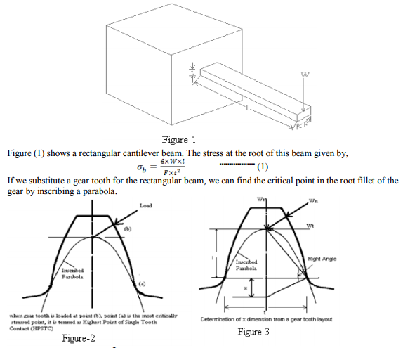
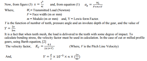
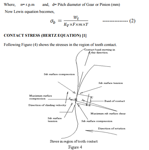
In the centre of the band, there is a point of maximum compressive stress. Directly underneath this point, there is a maximum subsurface shear stress. Just ahead of the band of contact, there is a narrow band of the compression and just behind the band of contact; there is a narrow region of tensile stress. A bit of metal on the surface of a gear tooth goes through a cycle of compression and tension each time, when a mating gear tooth passes over it. If gear tooth loaded heavily enough, and there will usually be evidence of both surface cracks and plastic flow on the contacting surface, and there may be a rupturing of the metal due to surface shear stresses. The stress on the surface of gear teeth are usually determined by formula derived from the work of H. Hertz?s; and these stresses are termed as Hertz stress. Hertz determined the width of the contact band and the stress pattern when various geometric shapes were loaded against each other. Considering figure (5),
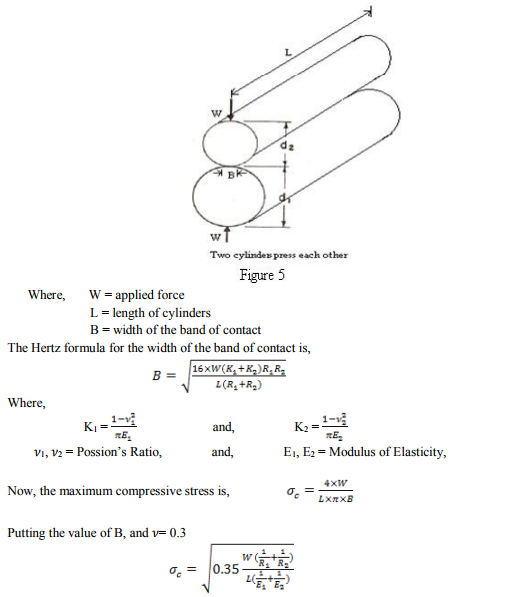
Above Hertz formula can be applied to Spur Gears quite easily by considering that the contact condition of gears are equivalent to those of cylinders having the same radius of curvature at the point of contact as the gear have. Ali Raad Hassan [8] presented formula for calculating Hertz equation for contact stresses in the pair of mating spur gear teeth. As figure (6)
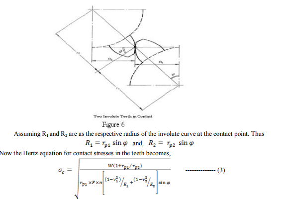
Where and are the pitch radius of the Pinion and Gear respectively and is the pressure angle. Equations (2) and (3) are use for quick calculation of Bending and Contact stress of a pair of mating gear efficiently. American Gear Manufacture Association (AGMA) provides the standard equations for calculating bending and contact stresses for a pair of mating gear including various factors. Following literature review gives a lot of information about stress calculation based on Lewis formula, Hertz theory, AGMA/ANSI (American National Standards Institute) equations and Finite Element Method.
LITERATURE REVIEW
Shuting Li (2002) researcher, performed loaded tooth contact analysis of a three dimensional, thin-rimed gear by presenting a method that combines the Mathematical Programming Method (MPM) with the 3-dimentional finite element method and compare the results with experiment. and concluded that FEM with MPM efficiently calculates bending stress in gears.[3] Andrzej Kawalec (2006) author gives comparative study of tooth-root strength evaluation methods used within International Standard Organization (ISO) and AGMA standards then verifying them with Finite Element method. The results allow for a better understanding of existing limitation in the current standards applied in engineering practice as well as provide a basis for future improvement of gear standard.[4] Jose I. Pedrero (2007) researcher used a nonuniform model of load distribution along the line of contact. He says if the load is, assume to be uniformly distributed along the line of contact, simple equations given by the linear theory of elasticity and the Hertzian contact model are not good agreement with experimental results. In this paper a non uniform model has been considered for stress analysis at contact ratio 2 and 2.5, and concluded that,
1. The critical tooth-root stress corresponds to contact at the inner point of the outer interval of the two pair tooth contact, and teeth loaded 60% of total transmitted load.
2. The critical contact stress corresponds to either one of the three following condition.
3. Contact at the inner point of contact and teeth loaded with 25% of the total transmitted load.
4. Contact at the inner point of the two pair tooth contact and teeth loaded with 40% of the total transmitted load.
5. Contact at the outer point of the inner interval of the two pair tooth contact, and teeth loaded with 60% of the total transmitted load.[5]
Shuting Li (2007) researcher presented 3- Dimentional Finite Element Method to conduct Surface contact stress (SCS) and Root bending stress (RBS) calculations for a pair of spur gear with Machining Error (ME), Assembly Error (AE) and Tooth Modification(TM). Moreover, found that ME, AE and TM exerts great effects on SCS and RBS of the gear. Results obtained by International Standard Organization (ISO) and Japan Gear Manufacturing Association (JGMA) standards are comparing with result of Finite Element Analysis. [6] Shuting Li (2008) researcher investigates the effect of addendum modification on contact strength, bending strength and basic performance parameters of spur gear. A face contact model of teeth and MPM and 3D finite element methods are used together to conduct loaded tooth contact analysis. He concluded that Hertz formula is not exact enough for the contact stress calculation because in engagement position the contact point is for away from the pitch point, also Hertz formula cannot be use for contact stress calculation of the gear at Tip or Root contact. Contact stress and contact width are changed slightly if addendum becomes longer and number of teeth is not changed.[7] Ali Raad Hassan (2009) author is analysed contact stress between two spur gear teeth in different contact position, between 0º to 30º. Start with an angle of 0º and end at 30º with an interval of 3º with corresponding length of contact and contact ratio. and found that a highest value of contact stress is at beginning of contact and then starts reducing until it reaches the location of single tooth contact. Result obtained by finite element analysis is compare with theoretical value which is found at geometrical contact point.[8] Rubin D. Chacon (2010) researcher analysed the contact stress between spur gear teeth using a plane model and validate Hertz stress and AGMA contact stress with finite element contact stress. Then concluded that FEM is able to simulate contact stress in a pair of mating gear, the contact stress is highest at higher point on the involute and lower at a single pair of teeth. Assume the full load transmitted and minimal at the pitch point of contact.[9] Konstandinos G. Raptis, (2010) author performed photo-elasticity test to determine stresses in a pair of mating gear. Obtained experimental results were comparing with the theoretical value of maximum stress at gear tooth root (when tooth is loaded at their most unfavorable contact point i.e. highest point of single tooth contact). Then concluded that the result obtained by the applied method is in reasonable value whereas it rises with increasing number of teeth on the large gear.[10] Wei Yangang,(2010) author provided a theoretical procedure for obtaining maximum contact stress at different point in meshing under the light of Hertz formula. and concluded that when the number of teeth on small gear is smaller than a certain value, the maximum contact stress in the meshing process is not generated in the inner critical point in the single tooth meshing region of the small gear.[11] Xianzhang FENG (2011) author use a precise model in large-scale CAD software and define the stress and displacement field to determine the maximum equivalent stress and maximum displacement. By defining the quasi-static characteristic of finite element model, shows that model can accurately simulate the distribution of equivalent stress and displacement change in the process of teeth meshing. The results are well agree with the actual meshing law and not only verify the correctness of model but also expect to dynamic analysis of gear.[12] Ignacio Gonzlez-Peraz (2011) researcher developed a finite element model and validate in terms of contact area, pressure distribution and maximum contact pressure for those cases where the Hertz theory can be applied and provide partial crowning to the finite element model where Hertz theory do not work properly. And concluded that analysis results gives good agreement with Hertz theory for calculating maximum contact pressure, contact area, and deflection with minute errors.[13] Ali Kamil Jabur, (2011) author investigates the characteristics of an involute gear system including contact stress between a pair of the gear from 3-dimansional analysis and compared the result with experimental data. Experimental setup uses DC servomotor and mounting the strain gauge in the tooth of the gear made by Polyimide materials. and concluded that increasing the spur gear design parameters (number of teeth with module) leads to improvement in the tooth strength and increasing the thickness of critical section and makes it able to withstand higher load.[14] S. Sankar, (2011) author used circular root fillet instead of standard trochoidal root fillet in gear. and concluded that the tooth deflection in the circular root fillet is less when compared to the trochoidal root fillet, further there is appreciable reduction in bending stress and contact shear stress for circular root fillet design in comparison to that of trochoidal root fillet design.[15] Seok- Chul Hwang (2011) author compared the variation of contact stress during rotation with contact stress at Lowest Point of Single Tooth Contact (LPSTC) and concluded that gear design that consider the contact stress in a pair of mating gear is more severe than that of the AGMA standard.[16] Massimiliano Pau (2012) researcher performed a tooth contact analysis, and contact area, contact pressure using an ultrasonic experimental setup. The results provide the information about the size and shape of the nominal contact area and contact pressure distribution. He concluded that the ultrasonic method has good potential as an effective tool in investigating contact problem in gear.[17]
CONCLUSION
The above literature review presents that the Finite Element Method is widely used for stress analysis in a pair of gear. In addition, FEM software has been use for performing meshing simulation. Almost in all of the above cases, contact stress calculation and Bending Stress calculation play more significant role in the design of gear. This study shows that Hertz theory is the basis of contact stress calculation and Lewis formula is use for calculating bending stress in a pair of gear. Theoretical result obtained by Lewis formula and Hertz equation and results found by AGMA/ANSI equations are comparable with Finite Element Analysis of spur gear.
References:
1. Darle W. Dudley, Practical Gear Design, McGraw-Hill Book Company, 1954
2. Peter R.N. Childs, Mechanical Design, Second edition, Elsevier ButterworthHeinemaan, 2004
3. Shuting Li, „Gear Contact Model and Loaded Tooth Contact Analysis of a ThreeDimensional Thin-Rimmed Gear? Journal of mechanical Design, ASME, 2002; vol.124/511.
4. Andrzej Kawalec, Jerzy Wiktor, Dariusz Ceglarek, „Comparative Analysis of Toothroot Strength Using ISO and AGMA Standard in Spur and Helical Gear With FEM-based Verification? Journal of mechanical Design, ASME, 2006; vol. 128/1141.
5. Jose I. Pedrero, Izaskun I.Vallejo, Miguel Pleguezuelos, „Calculation of Tooth Bending Strength and Surface Durability of High Transverse Contact Ratio Spur and Helical Gear Drives? Journal of mechanical Design, ASME, 2007; vol. 129/69.
6. Shuting Li, „Finite Element Analyses for Contact Strength and bending Strength of a pair of spur gears with Machining Errors, Assembly Errors and Tooth Modifications? Mechanism and Machine Theory, Elsevier, 2007; 42: 88-114.
7. Shuting Li, „Effect of Addendum on Contact Strength, Bending Strength and Basic Performance Parameters of a pair of Spur Gears? Mechanism and Machine Theory, Elsevier, 2008; 430: 1557-1584
8. Ali Raad Hassan,„Contact Stress Analysis of Spur Gear Teeth Pair? WASET 2009; 58
9. Rubin D. Chacon, Luis J. Adueza, „Analysis of Stress due to Contact between Spur Gears? Wseas.us, 2010
10. Konstandinos G. Raptis, Theodore N. Costopoulos „Rating of Spur Gear Strength using Photo elasticity and the Finite Element Method? American Journal of Engineering and Applied Sciences, 2010; 3(1): 222-231.
11. Wei Yangang, Zhang Xiujuan, Liu Yankui, „Theoretical research on the maximum Contact Stress of Involute spur Cylindrical Gear Pair in the External Meshing Process? IEEE,2010
12. Xianzhang FENG, „Analysis of field of Stress and Displacement in process of Meshing Gears? vol.5, 2011
13. Ignacio Gonzalez-Perez, Jose L. Iserte, Alfonso Fuentes, „Implementation of Hertz theory and validation a Finite Element Model for stress analysis of gear drives with localized bearing contact? Mechanism and Machine Theory, Elsevier, 2011; 46: 765-783
14. Ali Kamil Jebur, L.A.Khan, Y.Nath, „Numerical and Experimental Dynamic Contact of Rotating Spur Gear? Canadian Center of Science and Education, Modern Applied Science vol.5;2011
15. S. Sankar. Muthusamy Natraj, „Profile Modification- A Design approach for increasing the Tooth Strength in Spur Gear? International Journal of Advance Manufacturing Technology, Springer,2011; 55: 1-10.
16. Seok-Chul Hwang, Jin-hwan Lee, „Contact Stress Analysis for a pair of Mating Gears? Mathematics and computer modelling, Elsevier, 2011
17. Massimiliano Pau,Bruno leban, Antonio Baldi, Francesco Ginesu, „Experimental Contact pattern Analysis for a Gear-Rack system? Meccanica,Springer,2012; 47: 51-61
|





 This work is licensed under a Creative Commons Attribution-NonCommercial 4.0 International License