IJCRR - 3(4), April, 2011
Pages: 13-28
Print Article
Download XML Download PDF
THE EFFECT OF SPINDLE VIBRATION ON SURFACE ROUGHNESS OF WORKPIECE IN DRY TURNING
USING ANOVA
Author: S.Syath Abuthakeer, P.V. Mohanram, G. Mohan Kumar
Category: Technology
Abstract:There are remarkable forward strides in the manufacturing process with the tremendous technological innovations. In order to increase productivity, enhance quality and reduce cost, machine tool have to work free of any malfunction. Vibration responses are the proven measure of the malfunction. The main objective of this study is dedicated to the experimental vibration analysis of the spindle bearing assembly with self exited vibration. Experimental Modal analysis was carried out to obtain the natural frequency and vibration responses are investigated at various parametric levels and combinationsusing LabVIEW software. The parameters in the
investigation include feed, depth of cut, and cutting speed.Output parametris is surface finish and vibration level. Experimental data collected are tested with anlayis of variance(ANOVA) Taguchi design of experiments was used to optimize the process parameter for the responses,
surface roughness and vibration level. Regression model developed serves in prediction for the
responsesOn the completion of the experimental test ANOVA is used to validate the results.
Keywords: Spindle bearing, modal analysis, Surface roughness profile, vibration, LabVIEW, ANOVA
Full Text:
1. INTRODUCTION
Surface roughness is a commonly encountered problem in machined surfaces. It is defined as the finer irregularities of surface texture, which results from the inherent action of the production process. Consequently, surface roughness has a great influence on product quality, and the part functional properties such as lubricant retentivity, void volume, load bearing area, and frictional properties. Furthermore a good-quality machined surface significantly improves fatigue strength, corrosion resistance, and creep life[1]. Surface roughness is consisting of a multitude of apparently random peaks and valleys. When two rough surfaces are brought to be in contact, it is occurred in smaller area, which is called the real area of contact. This area is not only a function of the surface topography but also on the study of interfacial phenomena, such as friction and wears[2]. Surface finish plays an important role in affecting friction, wear, and lubrication of contacting bodies[3]. The effect of surface roughness on the lubricant film characteristics under conditions of combined normal and sliding motion [4]. Surface roughness is one of the parameters that greatly influence the friction under certain running conditions[5]. Surface roughness of the contacting surfaces influences the frictional properties of those surfaces during the forming processes [6]. It is clear now that surface roughness geometry strongly influences the manner in which the contacting surfaces are interacting. Furthermore, it is well known that the final geometry of surface roughness is influenced by various machining conditions such as spindle speed, feed, depth of cut, tool flank wear, and vibration level (chatter) [7]. One of the most significant factors affecting the performance of machine tools is chatter. Chatter not only limits productivity of cutting processes but also causes poor surface finish and reduced dimensional accuracy, increases the rate of tool wear, results in a noisy workplace and reduces the life of a machine tool. Several studies have been performed since the late 1950s regarding regenerative chatter [8, 9,10 and 11 ] These studies have led to a fundamental understanding of regeneration of waviness, or the overcutting of a machined surface by a vibrating cutter, as a feedback mechanism for the growth of selfexcited vibrations (or chatter). The study reveals, the larger the initial preload applied, the less vibration amplitudes are generated, and consequently less variation in the grinding depth of cut. As the initial preload increases, i.e., the stiffness of the bearing increases, the dominant frequencies of the system shift to higher values. As the preload increases up to a certain value, the peak to-peak amplitude decreases. Beyond this value the reduction in vibration amplitude is insignificant which indicates that larger values of preloading will not further reduce the vibration levels of the machine spindle. Therefore, this analysis can be used to calculate the optimum initial axial preload in order to obtain high accuracy for surface finish. The vibration levels of grinding machine spindle system increase significantly for grinding wheel wear rate percentage greater than 2, and decrease as the workpiece material hardness decreases [12] The tradeoff between preload, stifles and bearing life is exhibited. As the preload is increased, stiffness increases and the life of bearing decreases and as the preload decreases, stiffness is reduced and the machine tool performance is deteriorated. Vibration measurement serves as an effective tool for setting the preload during the assembly processes. There is no need to have a theoretical model as the required information can be obtain experimentally so that the method would not depend on the accuracy of a model. The frequency range investigated was around 1170 HZ[13] . The different component defects have their unique frequency, the amplitude denotes severity of the defect and the frequency reflects the source of the defect. Modern techniques for bearing diagnosis are directly applicable for machine tool. Gradual deterioration type of failure is suitable for machine condition monitoring, bearing failure is one example of the above mentioned failure type[14] . Self exited vibration domain is obtained through spectra of two accelerometers, one three axis accelerometer at the tool and the other accelerometer at the front bearing for displacement analysis of self exited vibration in turning. The cutting process of elastic machining system causes workpiece tool displacement that causes vibration, so resulting in modified chip size which reflects the dynamic instability. [15]. Today‘s manufacturing industry demands higher productivity with preserved or even smaller tolerances. The demand on high productivity leads to increased material removal per unit time and higher spindle speeds, increased feed rate, and greater depth of cut. However, at certain combinations of machining parameters; process instabilities and vibrations can occur which result in decreased accuracy, poorer surface finish, reduced tool life time and in the worst case spindle failure. Vibrations in milling have been investigated by many researchers using cutting force sensors, microphones and accelerometers. Although cutting force measurements may be addressed as the key information needed to be monitored, today‘s available force measuring platforms, dynamometers, are limited to relative small workpieces. Microphones are best suited for setting up thresholds based on experience or trials. The sound of a stable cutting process is usually calm and contains only frequencies originating from the spindle speed and the cutting teeth. However, microphones cannot give any information about deformations and forced vibrations. Since accelerometers easily be applied on the spindle bearing and measured the vibration level. Deterioration in the operation of a machine component gives rise to increasing in vibration level, mixing of vibration signals does not cause any loss of individual‘s frequency information. Vibration signature taken from appropriate location in machine tool can reveal the following defects: imbalance, misalignment, imperfect foundation, rubs, bearing defects, fault in belt drive etc. Piezoelectric transducer is lighter and has better frequency range for application, so the accelerometers are the best choice. The measures of the time based vibration analysis includes rms measurement, peak level (amount of impulse and bearing defect detection), crest factor, shock pulse, kurtosis (statistical movement of the probability density function of the vibration signal, phase. Trend analysis exhibits the rate of deterioration of vibration level in machine tool. The vibration reference standard is VDI 2056[16]. In this paper, a systematic procedure for measuring the vibration level of spindle bearing using LabVIEW software and optimize the machining parameters for possible improvement in the machining quality and vibration level. The vibration level was measured by using accelerometers and surface roughness values have been measured with a surface roughness tester (SE1200). The optimal values of the various machining parameters are determined through experimental investigation. The full factorial experimental design approach is utilized for experimental planning and ANOVA is employed to investigate the influence of machining parameters on the surface roughness and vibration level. The results obtained from the experimental study are utilized for analyzing and evaluating the effects of various input constraints at the optimal point. The effects of various constraints on the objective function are also analyzed through graphical picture. By using these graphs, significant effect of various input constraints on surface roughness and vibration level are highlighted. The selected optimal machining parameters and tits effectiveness are experimentally validated. The results obtained have shown the effectiveness of the proposed solution that have been analyzed and discussed in detail.
2. METHODOLOGY
The objective of the present work is to investigate the vibration response of the machine tool spindle at various operating conditions using Taguchi orthogonal array and develop a predicting bases for the responses: surface finish and vibration level.
The methodology adopted is presented in figure 1

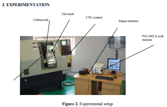
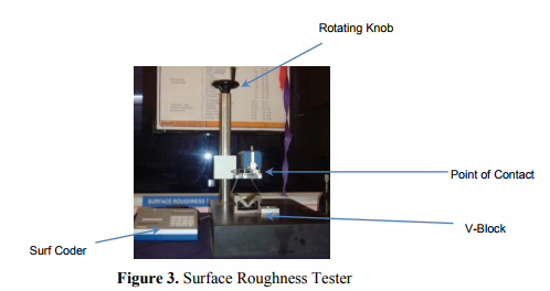
The experimental setup is shown in figure 2 It includes a CNC -Galaxy –MIDAS-0 turning centre, a CCGT-09T30FL (Taegu Tec) turning insert, tool holder SCLC L2020 K09 T3(Taegu Tec), a work piece (Al 6063 aluminum, Diameter 38 mm x 70mm length) without any cutting fluid. Accelerometer is embedded on spindle bearing ( Bruel and Kjaer 9.88mV/g- type 4517). The accelerometer signals are taken to NI PXI 1042 – Q Data Acquisition Card system using LabVIEW software. The vibration data was captured by Data Acquisition Card system. This system included hardware selection, circuit design and implementation, hardware interface, circuit troubleshooting, filtering, computer software programming, system integration, and testing in real CNC turning processes. The following three sections describe the development of the hardware system, software system, and integrating and testing of the data acquisition system along with the vibration data analyses. Surface roughness was measured using surface roughness tester as shown in figure 3.
3.1 HARDWARE SYSTEM
Vibration signals are important for monitoring spindle bearing vibration in turning process for measuring vibration amplitude in terms of accelerations (mm/s2-levels). A computer code has been developed in LabVIEW for data acquisition, data storage and display. Fast Fourier Transform (FFT) computation algorithm was included in the computer program to extract the vibration amplitude in the time and frequency domain, which will be explained in software development section. Accelerometers: Converts the physical acceleration into a voltage signal Signal conditioning circuit: Amplifies the voltage signal and improves the resolution Personal computer: Runs the program, stores and display at any desired instant of time.
3.2 SOFTWARE SYSTEM
The software in this system consists of the following components. An NC program that directs the CNC turning machine to cut the work piece. Vibration data analysis and Fast Fourier Transform (FFT) analysis Main objective of the research work is to monitor the vibration level spindle bearing. So it is assumed that the condition of the machine and its components is good in all other aspects such as foundation of the machine, rigidity of the machine components (such as bed, cutting tool , tail stock etc.) and so on. The simplest vibration analysis is conducted through collecting the ?overall? vibration amplitude Root Mean Square (RMS) value and plotting the vibration data in time domain and frequency domain. The ?overall? signal represents the total energy content of all vibration sources at all frequencies.
3.3 INTEGRATION AND TESTING OF THE DATA ACQUISITION SYSTEM
The Integration and testing of the data acquisition system is shown in figure 2.When tested in a machining workpiece, the sensor was protected to prevent any interference caused due to machining condition.
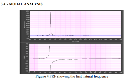
Any physical system can vibrate, the frequencies at which vibration naturally occurs, and the modal shapes which the vibrating system assumes are properties of the system, and can be determined using modal analysis. Modal analysis is frequently utilized to abstract the modal parameters of a system, including natural frequencies, mode shapes and modal damping ratio. Since these parameters depend only on the system itself but dominate the response of the system to excitations, modal analysis is the fundamental response analysis and has therefore gained increasing attentions. In the modal analysis, an impact hammer (PCB-086C03) was used to excite the spindle. An accelerometer was mounted on the spindle and interfaced with a data acquisition card and LabVIEW software to record the response of the spindle. The impact pulse indicating the magnitude of input force was generated by the impact hammer. The frequency domain response was obtained by using signal analyzer available in sound and vibration toolkit of Lab VIEW as shown in figure 4. From the figure 4, it is evident that, the fundamental natural frequency of the spindle is about 600Hz.
3.5 DYNAMIC ANALYSIS
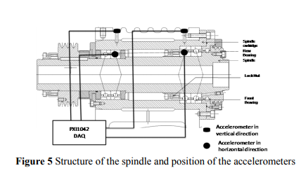
The vibration analysis was done under actual machining conditions. The accelerometer mounted in spindle was used to collect the vibration signals. The position of accelerometer is shown in the figure 5. The LabVIEW acquires the vibration signals and stored the signals continuously frame by frame at every stage of cutting in on-line. The dynamic response of accelerometer is given in table 1.
4.0 EXPERIMENTAL DESIGN Experimental design approach is selected for the investigations of varying three controllable parameters at three levels, since 3k factorial design is efficient to study the effects of two or more factors. Without loss of generality three levels of factor are referred as Low, Intermediate and High and levels are designed by digits 0,1 and 2. Each treatment combination in the 3k design is denoted by k digits where the first digit indicates a level of factorial A (cutting speed), B (depth of cut), indicates the level of factorial second and C (feed) indicates the level of three. These factors as well as their levels identified are given in table 2.

5.0 RESULTS AND DISCUSSION
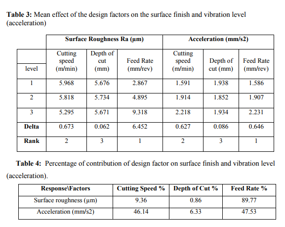
The vibration phenomenon for various cutting parameters has been analyzed using LabVIEW software. The plan of the experiment was developed to assess the effect of cutting speed, feed rate and depth of the cut on the surface roughness value and vibration level. Table 1 illustrates the experimental result of surface roughness value and vibration level. One of the objectives of this study is to find the important factors and combination of factors influencing the vibration level using the lower the better characteristics. The experimental results were analyzed using analysis of variance (ANOVA), which is used for identifying the factors significantly affecting the performance measures. The results are analyzed with MINITAB software. The result of ANOVA analysis reflect that feed rate is the most contributing factor for the responses surface roughness and vibration level followed by cutting speed and depth of cut. According to the ANOVA response the best regression equation (1 and 2) obtained for surface finish and vibration level. The mean effect of the design factors on the surface finish and vibration is shown in table 3
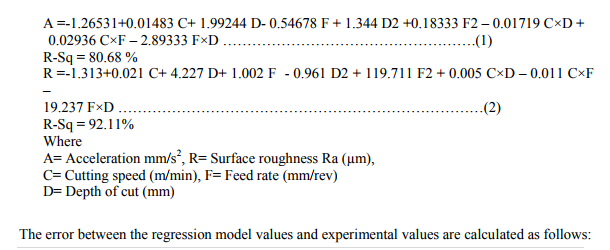

The error rate of this model is calculated by using equation number 3. The percentage error associated with each experiment is observed to be lower and is well with the limit within a reasonable degree of approximation. Percentage of contribution of each parameter on surface finish and vibration level in terms of acceleration is shown in table 4
5.1 MAIN EFFECT, INTERACTION PLOT AND CONTOUR PLOT
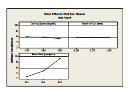
The main effect plot and the interaction plots (between Depth of cut, Cutting speed, Feed rate and surface roughness value and vibration level have been shown in figure 6 to 13 . Figure 6 shows the main effect plot for surface finish value for various depth of cut, cutting speed and feed rate, where the left side is for the cutting speed. It indicates that surface roughness decreases with increase of cutting speed and starts increasing , with increase of feed and has very low influence on the depth of cut since delta value is found to be very low.
5.2.1 INTERACTION PLOT
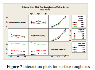
The interaction chart are plotted to visualize the effect of interaction within the factors. The interaction charts are presented in figure 7 for the responses surface finish. The parallel trends of the lines clearly show very little interaction between the factors and also reflect that the parallel trends of the lines clearly shows very little or no interaction between the two parameters.
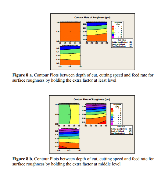
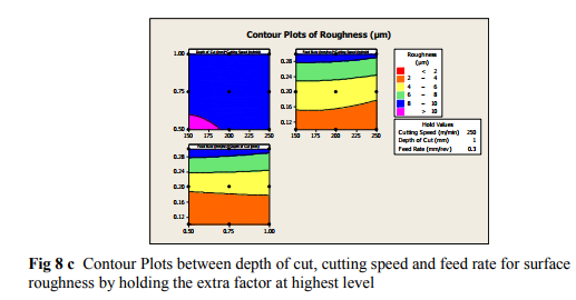
5.2.2 CONTOUR PLOTS OF SURFACE ROUGHNESS
Contour plot is shown in figure 8, it is a graphical technique used to explore the relationship between three variable on a single plot and to view combinations of x and y that produce desirable response value of surface roughness value.

5.2.3 SURFACE PLOTS OF SURFACE ROUGHNESS
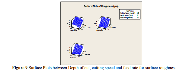
The combined effect of depth of cut, cutting speed and feed rate on surface roughness value can be assessed by drawing a 3-D Plot shown in figure 9. It can be observed from the plot that the effect of depth of cut, cutting speed and feed rate on surface roughness is more pronounced 3 D plots have been plotted to investigate influence of two factors on the response. This is plotted for middle value. Surface finish tends to the minimum values when depth of cut, cutting speed and feed rate is minimum.
5.3 MAIN EFFECT, INTERACTION PLOT AND CONTOUR PLOT- VIBRATION LEVEL
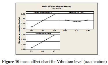
Figure 10 shows the main effect plot for vibration level for various cutting speed, depth of cut and feed rate, where the left side is for the cutting speed. It indicates that vibration level increases with increase of cutting speed and starts increasing, with increase of feed and has very low influence on the depth of cut since delta value is found to be very low.
5.3.1 INTERACTION PLOT
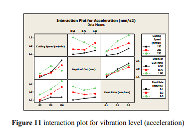
The interaction chart are plotted to visualize the effect of interaction within the factors. The interaction charts are presented in figure 11 for the responses vibration level. The parallel trends of the lines clearly show very little interaction between the factors and also reflect that the parallel trends of the lines clearly shows very little or no interaction between the two parameters.
5.3.1CONTOUR PLOTS OF VIBRATION LEVEL
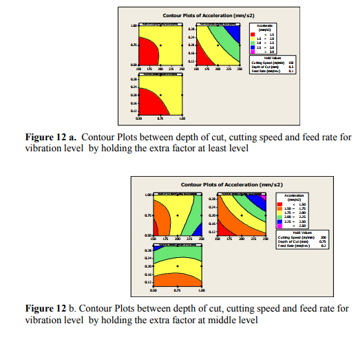
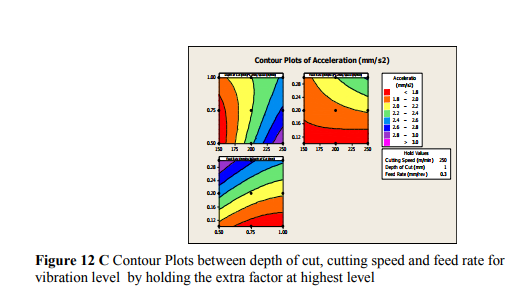
Contour plot is shown in figure 12, it is a graphical technique used to explore the relationship between three variable on a single plot and to view combinations of x and y that produce desirable response value of vibration level.
5.3.2 SURFACE PLOTS OF VIBRATION LEVEL
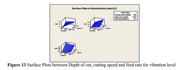
The combined effect of cutting speed, depth of cut and feed rate on vibration can be assessed by drawing a 3-D Plot shown in figure13. It can be observed from the plot that the effect of cutting speed, depth of cut and feed rate on vibration level is more pronounced 3 D plots have been plotted to investigate influence of two factors on the response. This is plotted for middle value. Vibration level tends to the minimum values when Depth of cut, cutting speed and feed rate is minimum.
6. 0 CONCLUSIONS
In this course of study, Experiments were conducted on CNC lathe using CCGT- 0930FL carbide turning insert, machining variables such as surface finish value and spindle bearing vibration in were measured in CNC machining processes based on the vibration signal collected through a LabVIEW data acquisition system. The effect of cutting parameters such as cutting speed, depth of cut and feed rate on machining variables is evaluated. Based on the current study, the following conclusions can be drawn:
- From the modal analysis the signals peaks exhibit response in a particular natural frequency range is 600 Hz
- It is observed that the natural frequency shifts away from the operating frequency thereby avoiding the resonance condition of spindle.
- The Fast Fourier Transform(FFT) function and its graphic display were integrated in to the software program developed by LabVIEW. Data were visualized in real-time
- The method presented effectively measure surface finish and vibration of spindle bearing. The goal of this research is successfully met.
- A multiple regression model has been developed and validated with experimental results.
- An analysis of variance (ANOVA) was made and it was found that the feed rate (89.77) , Cutting speed (9.36%) depth of cut (0.86% contribution), has greater influence on surface finish value. From the experimental results demonstrate that the feed rate and cutting speed are the main parameters among the three controllable factors (depth of cut, cutting speed and feed rate) that influence the surface finish value of component.
- It was found that the feed rate (47.53%) , Cutting speed (46.14%) depth of cut (6.33%), has greater influence on vibration level
. From the experimental results demonstrate that the feed rate and cutting speed are the main parameters among the three controllable factors (depth of cut, cutting speed and feed rate) that influence the vibration level .
- Contour plot shows the relationship between three variables on a single plot. It also helps in viewing combinations of x and y that produce desirable response values of surface finish and vibration level
. - Hence, this study helps to promote the operational use of ANOVA for land cover classification
References:
1. Stark and Moon, 1999 G.A. Stark and K.S. Moon, Modeling of surface texture in the peripheral milling process, using neural network, spline, and fractal methods with evidence of Chaos, Trans. Of the ASME, J. Manuf. Sci. Eng. 121 (1999), pp. 251-256.
2. Bhushan, 1999 B. Bhushan, Handbook of Micro-Nano Tribology, CRC Press (1999).
3. Lee and Ren, 1996 S.C. Lee and N. Ren, Behavior of elastic-plastic rough surface contacts as affected by surface topography, load, and material hardness, Tribol. Trans. 39 (1) (1996), pp. 67-74.
4. Lundberg, 1995 J. Lundberg, Influence of surface roughness on normal-sliding lubrication, Tribol. Int. 28 (5) (1995), pp. 317-322.
5. Xiao Li et al., 2003 B. Xiao Li, G. Rosen, Naser Amini and H. Nilsson Per, A study on the effect of surface topography on rough friction in roller contact, J. Wear 254 (2003), pp. 1162- 1169.
6. Mahrenholtz et al., 2005 O. Mahrenholtz, N. Bontcheva and R. Iankov, Influence of surface roughness on friction during metal forming processes, J. Mater. Process. Technol. 159 (2005), pp. 9-16.
7. Selmy et al., 1989 A.I. Selmy, I. ElSonbaty, F. Shehata and U.A. Khashaba, Some factors affecting the accuracy of turned parts, Scientific Bulletin of the Faculty of Engineering vol. 24 (2), Ain Shams University, Egypt (1989) pp. 356-368.
8. S. Tobias and W. Fishwick, Theory of regenerative machine tool chatter, The Engineer February (1958).
9. J. Tlusty, M. Polacek, The stability of machine tools against self-excited vibrations in machining, in: Proceedingsof the ASME International Research in Production Engineering, Pittsburgh, USA, 1963, pp. 465-474.
10. H. Merritt, Theory of self-excited machine tool chatter, Transactions of ASME Journal of Engineering for Industry 87 (1965), pp. 447-454.
11. Y. Altintas and E. Budak, Analytical prediction of stability lobes in milling, CIRP Annals 44 (1995) (1), pp. 357 362.
12. Mohammed A. Alfares, Abdallah A and Elsharkawy (2003). Effects of axial preloading of angular contact ball bearings on the dynamics of a grinding machine spindle system. Journal of Materials Processing Technology 48- 59.
13. M.A. Mannan and B.J. Stone (1998). The use of vibratio measurement for quality controle of machine tool spindle. Int J Adv Manuf Technol 14: 889-893.
14. S. Saravanan, G.S. Yadava and P.V. Rao. (2006) Condition monitoring studies on spindle bearing of a lathe. Int J Adv Manuf Technol 28: 993-1005.
15. Claudiu F. Bisu, Philippe Darnis, Alain Gérard and Jean-Yves K'nevez. (2008) Displacements analysis of self-excited vibrations in turning. Int J Adv Manuf Technol, pp 126-135.
16. K N GUPTA (1997). Vibration - A tool for machine diagnostics and condition Monitoring. Sadhana, Vol. 22, Part 3, pp. 393-410.
|


 This work is licensed under a Creative Commons Attribution-NonCommercial 4.0 International License