IJCRR - 4(7), April, 2012
Pages: 52-58
Date of Publication: 18-Apr-2012
Print Article
Download XML Download PDF
DESIGN AND ANALYSIS OF COMPACT CPW-FED UWB ANTENNA FOR WIRELESS COMMUNICATION
APPLICATIONS
Author: D. Ujwala, B.T.P.Madhav, J. Rajanikanth, B.Jyothi, B.Harish, H.M.Ramesh
Category: Technology
Abstract:For the exchange of high data rate information, wide band antennas are needed and their usage increased tremendously now a days. A compact antenna of size 22mm x 26mm x 1.6mm is proposed with serrated radiating patch and ground fed by Coplanar Waveguide Feedline (CPW). The proposed antenna concedes a wide bandwidth from 3.2 GHz to 10.8 GHz with return loss less than -10dB, VSWR less than 2 and has Omni directional radiation pattern with good radiation efficiency in the operating bandwidth. The proposed antenna is simulated using FEM based Ansoft HFSSv13 and the results are analyzed.
Keywords: Coplanar Waveguide, UWB antenna, VSWR, Omni directional pattern, Radiation efficiency
Full Text:
INTRODUCTION
Ultra wideband communication systems have incurred great attraction in wireless world. Recently, a tremendous attention has been focused on these UWB communication systems since they are capable for exchanging high rate information. The Federal Communication Commission allocated a bandwidth from 3.1 GHz to 10.6 GHz for UWB systems [1] in 2002. The major challenges in the design of UWB antenna are Compact size, Omni directional pattern and stable gain along with wide bandwidth [2] and high speed data rate. The UWB antenna provides secured signal transmission, immunity to interference and low power consumption. UWB antennas are integrated in systems where band notch characteristics are needed [3-4]. Parasitic elements added to the antenna provide broad bandwidth but increases size of antenna [5]. The planar monopole antennas [6-8] are better for UWB applications due to compact size and static radiation pattern. UWB antennas can be implemented with microstrip line [9] or CPW [10]. The CPW antennas are useful for microwave and millimeter applications since they offer low profile and ease of integration with circuits. Few other applications of UWB antenna are position location and tracking, automotive sensors, collision avoidance sensor in vehicles etc. In this paper, we have proposed a planar monopole antenna with CPW feed with a wide bandwidth from 3.2 GHz to 10.8 GHz. It provides nearly Omni-directional pattern, high radiation efficiency and approximately stable gain.
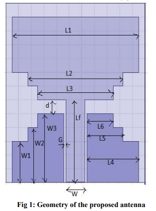
ANTENNA STRUCTURE:The geometry of the proposed CPW-fed antenna is shown in Figure 1. The antenna is printed on a FR4 substrate with dielectric constant εr=4.4, loss tangent δ=0.02 and thickness h=1.6mm. The serrated radiating patch consists of three rectangles of lengths L1, L2, L3 and widths W1, W2, W3 respectively. The ground plane is a combination of three rectangles of lengths L4, L5, L6 and widths W1, W2, W3 respectively on either side of CPW feed line. The gap between the radiating patch and ground plane is d=2mm. The antenna is fed by a 50? CPW line with a feed line length Lf, strip width W and gap G. The various configuration parameters of the antenna are L1=20mm, L2=15mm, L3=12mm, L4=8.15mm, L5=5.65mm, L6=4.15mm, W1=8mm, W2=2mm, W3=2mm, Lf=12mm, d=2mm, G=0.35mm, W=3mm, h=1.6mm, εr=4.4
RESULTS AND DISCUSSIONS
The Return Loss is less than -10dB from 3.2 GHz to 10.8 GHz as shown in Figure 2 and resonates at three frequencies 3.92 GHz, 6.24 GHz and 10.08 GHz whose return losses are -33dB, -17dB and - 16dB respectively.
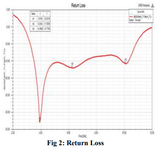
Figure 3 shows the VSWR plot and it is less than 2 in the operating bandwidth. Figure 4 is a Gain versus Frequency plot with a maximum gain of 4.1dBi at 8 GHz and gain is approximately stable in the operating bandwidth.
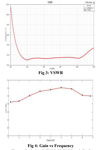
Figure 5 shows E-Field, H-Field and Surface current distributions on the patch and ground of the antenna at 3.92 GHz, 6.24 GHz and 10.08 GHz. Figure 6 shows the Mesh Plots on the patch and ground of the antenna at 3.92 GHz, 6.24 GHz and 10.08 GHz. For each mode, there are two orthogonal planes in the far field region. One designated as E-plane and the other designated as H-plane. The far zone electric field lies in the E-plane and the far zone magnetic field lies in the H-plane. The patterns in these planes are referred to as the E and H plane patterns respectively. Figure 7 shows the co-polarization and cross-polarization radiation patterns in E-Plane and H-Plane at 3.92 GHz, 6.24 GHz and 10.08 GHz respectively. Figure 8 shows the contour plots for different values of theta versus phi.
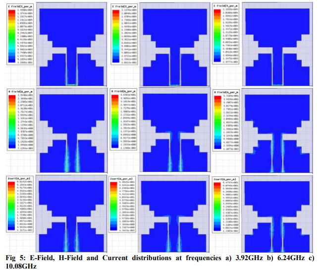
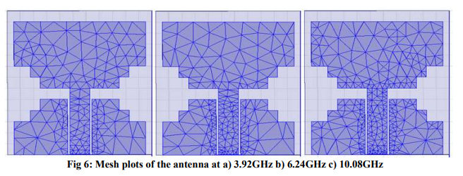
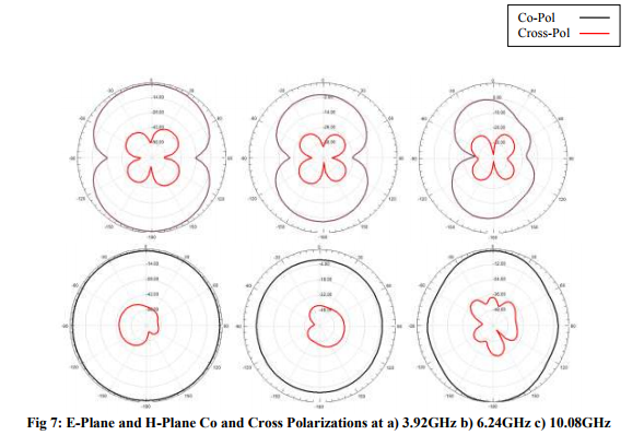
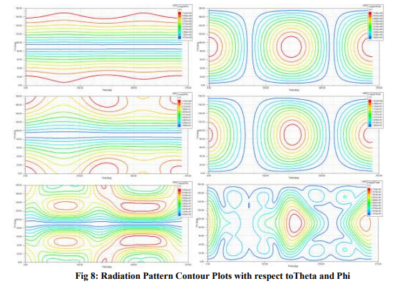
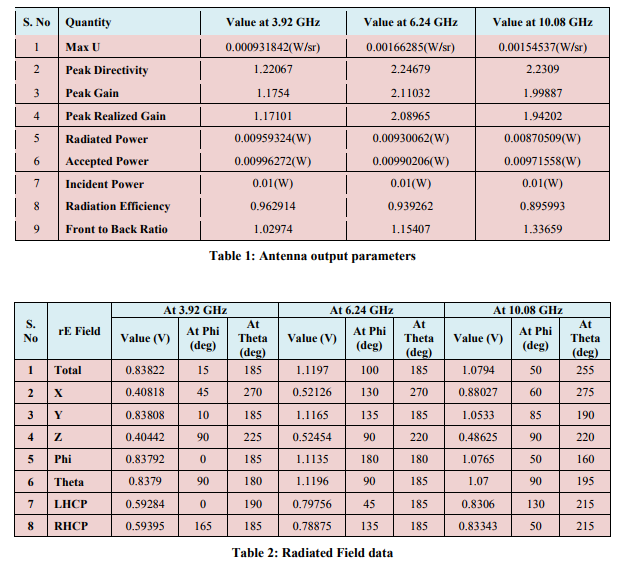
Table 1 shows antenna output parameters like Peak Gain, Peak Directivity, Radiated Power, Radiated Efficiency etc at three resonant frequencies at 3.92 GHz, 6.24 GHz and 10.08 GHz. Table 2 shows radiated field data at Phi and Theta angles at those three resonant frequencies.
CONCLUSION
A Compact CPW-fed UWB antenna for wireless applications is designed and analyzed using Ansoft HFSS vs.13. Antenna resonates at three frequencies 3.92 GHz, 6.24 GHz, 10.08 GHz. The antenna exhibits Omni-directional radiation pattern in H-Plane and quasi Omni-directional pattern in E-Plane. It is observed that cross polarization is less than co-polarization in E and H Planes. ACKNOWLEDGEMENTS We would like to express our gratitude towards the Management and Department of ECE, K.L.University for their support during this work.
References:
1. FCC, First report and order in the matter of revision of part 15 of the Commission's rules regarding ultra-wideband transmission systems, FCC, Washington, DC, ET-Docket 98- 153, 2002.
2. K.L. Wong, Compact and broadband microstrip antennas, Wiley, Hoboken,NJ 2002.
3. G. M. Zhang, J. S. Hong, B. Z. Wang, Q. Y. Qin, J. B Mo, and D. M. Wan, ?A novel multi folded UWB antenna fed by CPW,? J. of Electromagn. Waves and Appl., Vol. 21, No. 14, 2109-2119, 2007.
4. Shi-Wei qu, Jia–Lin Li, and Quan Xue, ?A band notched ultra wide band printed monopole antenna,? IEEE Antennas Wireless Propa. Lett., vol. 5, pp. 495-498, 2006.
5. K. F. Jacob, M. N. Suma, R. K. Raj, M. Joseph and P. Mohanan, ?Planar branched monopole antenna for UWB applications,? Microw. Opt. Technol. Lett., Vol. 49, no. 1, pp 45-57, Jan. 2007.
6. Y. J . Cho, K. H. Kim, D. H choi, S. S. Lee and S. O. Park, ?A miniature UWB planar monopole antenna with 5-GHz band rejection filter and time domain characteristics,? IEEE trans. Antennas Propag., vol.54, pp. 1453-1460, Mar. 2006.
7. W. S. Lee, D. Z. Kim, K. J. Kim and Y. W. Yu, ?Wideband planar monopole antenna with dual band–notched characteristics?, IEEE trans. Antennas Propag., vol.54, no. 6, pp. 2800-2806, Jun. 2006.
8. Reza Zaker, Changiz Ghobadi and Javad Nourinia, ?Novel modified UWB planar monopole antenna with variable frequency band-notch function?, IEEE Antennas Wireless Propag. Lett.,, vol. 7, pp. 112-114, 2008.
9. Jen-Yea Jan, Liang-Chih Tseng, "Small Planar Monopole antenna With a Shorted Parasitic Inverted- L Wire for Wireless Communications in the 2.4, 5.2 and 5.8 GHz Bands," IEEE Trans. Antennas and Propagation, vol. AP-52, no. 7, pp. 19031905, July 2004.
10. Jon II Kimker and Yong Jee, ?Design of Ultra wideband Coplanar waveguide-fed LIshape planar monopole antennas?, IEEE Antennas Wireless Propag. Lett.,, vol. 6, pp. 383-387, 2007.
|
 IJCRR
IJCRR 


 This work is licensed under a Creative Commons Attribution-NonCommercial 4.0 International License