IJCRR - 4(7), April, 2012
Pages: 45-51
Print Article
Download XML Download PDF
EXPERIMENTAL ANALYSIS OF THE EFFECT OF FIN GEOMETRY ON HEAT TRANSFER RATE THROUGH THE REFRIGERATOR CONDENSER
Author: G. Kiran Kumar
Category: Technology
Abstract:A refrigerator is a machine which attains and maintains the temperature of a space below that of surroundings by transferring heat from the space to be cooled to the surroundings with the help of a compressor. Majority of the refrigerators works on the vapor compression refrigeration system which consists of components like compressors, condensers, expansion valve and evaporator. The performance of the system depends on the performance of all the components of the system. A condenser is a heat exchanger where the refrigerant is first desuperheated and then the saturated vapor condenses into liquid state. This is an important part of the refrigeration cycle without which the refrigerant cannot be recycled. In general all the domestic refrigerators have naturally air cooled condensers. Heat transfer from suchcondensers can be increased by the extended surfaces called fins. The rate of heat transfer through
condenser depends on fin material, spacing between the fins, geometry of the fins and it's thermal conductivity. This experimental work focuses on the effect of condenser fin geometry on the performance of the condenser. Experiments are conducted with circular and rectangular cross sectional fins fabricated to the condenser of 165 lts capacity refrigerator. Heat transfer rate through the condenser is calculated for different fin geometries.
Full Text:
INTRODUCTION
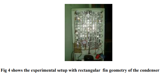
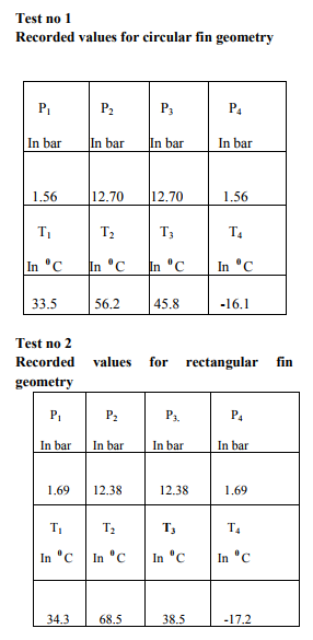
A condenser is a heat exchanger is which desuperheating of high temperature vapor changes the phase from vapor to liquid and sub cooling of condensate occurs. The condenser is an important device used in the high pressure side of a refrigeration system. Its function is to remove heat of hot vapor refrigerant discharged from the compressor. The hot vapor refrigerant consists of the heat absorbed by the evaporator and the heat of compression added by the mechanical energy of the compressor motor. The heat from the hot vapor refrigerant in a condenser is removed first by transferring it to the walls of the condenser tubes and then from the tubes to the condensing or cooling medium. The cooling medium may be air or water or a combination of the two. An air cooled condenser is one in which the removal of heat is done by air. It consists of steel or copper tubing through which the refrigerant flows. The size of tube usually ranges from 6mm to 18mm outside diameter, depending upon the size of the condenser. Generally copper tubes are used because of its excellent heat transfer ability. The condensers with steel tubes are used in ammonia refrigerating systems. Majority of the domestic refrigerators uses the natural convection air cooled condenser. In the present work refrigerator uses the natural convection air cooled condenser. In natural convection air cooled condenser, the heat transfer from the condenser coils to the air is by natural convection. As the air comes in contact with the warm condenser tubes, it absorbs heat from the refrigerant and thus the temperature of air increases. The warm air being lighter, rises up and cold air from below rises to take away the heat from the condenser. This cycle continues in natural convection air cooled condensers. This paper is an experimental approach to increase the heat transfer through the condenser with different fin geometry . If the condenser is having circular fins the heat transfer through the condenser is less. Because of it small surface area. On the other hand if the condenser is having rectangular fins the heat transfer through the condenser is more, because of its more surface area.
PRESENT WORK:
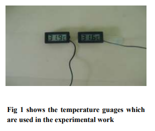
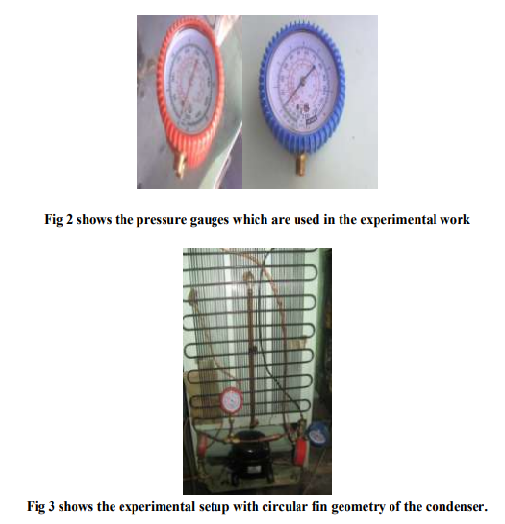
The procedure for the present work is as follows. In vapor compression refrigeration system basically there are two heat exchangers. One is to absorb the heat which is done by evaporator and another is to reject the absorbed heat in the evaporator to the surroundings. The work focuses on more heat transfer through the condenser. This is only possible either by providing a fan or extending the surfaces. The extended surfaces are called fins. The rate of heat transfer through the condenser depends upon the number of fins and fin geometry attached to the condenser. The present work investigates the rate of heat transfer through the condenser using different fin geometry. In the present domestic refrigerator of the condenser fins are circular and rectangular are used and compared. In order to know the performance characteristics of the vapor compression refrigeration system pressure and temperature gauges are installed at each entry and exit of the component. Experiments are conducted on different fin geometry of the condenser. All the values of pressures and temperatures are tabulated. The domestic refrigerator selected for the present work has the following specifications.
Capacity of refrigerator - 165liters
Refrigerant used - R134a
Compressor - 1/7 HP Hermetically
Capacity sealed.
Condenser
Length - 8.5m
Diameter - 6.5mm
Evaporator
Length - 7.62m
Diameter - 6.5mm
Capillary tube
Length - 2.128m
Diameter - 0.8mm
Calculations and analysis:
Where
P1 = Compressor suction pressure
P2 = Compressor discharge pressure
P3 = Condensing pressure
P4 = Evaporator pressure
T1 = Compressor suction temperature
T2 = Compressor discharge temperature
T3 = Condensing temperature
T4 = Evaporator temperature
Analysis of the condenser:
Thermal analysis in the heat exchangers can be done in two ways.
1. LMTD Method (Logarithmic Mean Temperature Difference)
2. NTU Method ( Number of Heat transfer Units)
LMTD Method is useful when the inlet and outlet fluid temperatures of condenser and air are known. NTU Method is useful when the heat exchanger is designed for the particular mass flow rate. For the given conditions LMTD Method is suitable.
LMTD Method:
In a heat exchanger, the temperature of the heating and cooling fluids do not in general, remain constant, but vary from point to point along the length of the heat exchanger. Since the temperature difference between the two fluids keeps changing, the rate of heat transfer also changes along the length of the heat exchanger as shown.

The rate of heat transfer can be calculated from the relation
Q = U A ?T
Since ?T changes from point to point in a heat exchanger, we propose to use ?Tm, a suitable mean temperature difference between the two ends of a heat exchanger. The rate of heat transfer can be rewritten as Q = U A ?Tm
Where ?Tm = Log Mean Temperature Difference (LMTD) A = surface area of condenser in m2 = ΠDL ?Tm = (?T1-?T2)/ln (?T1/?T2) Where ?T1 = Th1-TC1 ?T2 = Th2-TC2 Th1 =Refrigerant temperature at Condenser inlet Th2 = Refrigerant temperature at Condenser outlet Tc1 = Air temperature at the condenser inlet Tc2 = Air temperature at the condenser outlet
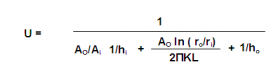
Where U = overall heat transfer coefficient in w/m2 k Ao = outside tube Area in m2 Ai = inside tube Area in m2 hi = convective heat transfer coefficient of R-134(a) in W/m2 k ho = convective heat transfer coefficient of Airin w/m2 k = 10 W/m2 k ro = outside radius of pipe in m ri = inside radius of pipe in m K = thermal conductivity of copper in W/m-k If Ao = Ai the above equation can be reduced to U = 1/ (1/ hi + 1/ ho)
Properties of R-134(a) are taken at bulk mean temperature of condenser with different fin geometry. Bulk mean temperature of condenser can be calculated by = (Condenser inlet temp. + Condenser outlet temp.)/2 In order to calculate convective heat transfer coefficient of R-134(a) the following steps are to be followed and the convection is of forced convection pipe flow with respect to refrigerant.
ReD = (ρVD)/μ
Pr = (μ Cp)/K
Where
ReD = Reynolds number
ρ = Density of R-134(a) in kg/m3
V = Velocity in m/sec = 3 to 4 m/sec
D = Diameter of the pipe in m
μ = Viscosity in pa-s
Cp = specific heat in J/kg K
K = thermal conductivity in W/m K
Forced convection correlations in turbulent pipe flow are given by Dittus-Boelter
NuD = 0.023ReD 4/5 Prn
NuD = hiD/K
Where
D= Diameter of the pipe = 6.5x10⁻³m
Pr = Prandtl number
n = 0.4 for heating of the fluid and 0.3 for cooling of the fluid The Dittus-Boelter equation is valid for
0.7< Pr < 160 and Red >10000
The Dittus-Boelter equation is good approximation where temperature differences between bulk fluid and heat transfer surface are minimal
.Nusselt number:
In heat transfer at boundary (surface) within a fluid, the Nusselt number is the ratio of convective to conductive heat transfer across (normal to) boundary. Named after Wilhelm Nusselt, it is a dimensionless number. A Nusselt number is close to one for slug or laminar flow. It varies for turbulent flow. For forced convection, the Nusselt number is generally a function of the Reynolds number and prandtl number, or Nu = f (Re, Pr).
Calculation of overall heat transfer coefficient Condenser coil dimensions: Outer diameter of tube = 6.5mm Inner diameter of tube = 6mm
For Test -1
Refrigerant temperature at condenser inlet = 56.20C
Refrigeranttemperature at condenser outlet =45.80C
Air temperature at the condenser inlet = 33.20 C
Air temperature at the condenser outlet = 34.20 C
For Test -2
Refrigerant temperature at condenser inlet = 68.50C
Refrigeranttemperature at condenser outlet =38.50C
Air temperature at the condenser inlet = 31.20 C
Air temperature at the condenser outlet = 32.20 C
Calculations:
Inside heat transfer coefficient for condenser coil Sizes of tube: Outer diameter of tube = 6.5mm Inner diameter of tube = 6mm
For Test -1
Condenser entering temperature = 56.2 0 C
Condenser leaving temperature = 45.8 0 C
Air temperature at the condenser inlet = 33.20 C
Air temperature at the condenser outlet = 34.20 C
Mean temperature = (56.2 +45.8)/2 = 56 0C
Mean temperature = 560C at this temperature properties of From R-134a are From R-134a refrigerant property tables
ρ = 1073.0 kg/m3
D = 6.5 X 10⁻³ m
μ = 146.1 X 10⁻⁶ pa-.s
V = 3.5 m/s
K = 67.6x 10⁻³ W/m k
Cp= 1.621 x10³ J/kg k
ReD = (ρvD)/
μ = (1073x3.5x6.5 X 10-3 )/ 146.1X 10-6 = 1.67x10⁵ Pr = (μ Cp)/K = (146.1 x10-6 x1. 621x103 )/ (67.6x10⁻³ ) = 3.503 NUD = 0.023ReD 4/5 Prn = 0.023x (1.67 x105 ) 4/5 x (3.503)0.3= 504.932 NuD = hiD/K 516.514 = (hi 6.5 X 10⁻³ )/ 67.6x10⁻³ hi = 5251.29 W/m2 k
U = 1/ (1/ hi + 1/ ho) = 1/(1/5251.29 + 1/10) = 9.981
W/m2K ?Tm = (?T1-?T2)/ln(?T1/?T2) =(23-11.6)/ln(23/11.6) =16.650 c
?T1 = Th1-TC1= 56.2-33.2 = 230 C ?T2 = Th2-TC2 = 45.8-34.2 = 11.60 C ?Tm = (23-11.6)/ln(23/11.6) = 16.654oC Q =Heat transfer rate through the condenser = U A ?Tm Q= 9.998xπx6.5x10-3 x8.5x16.654 = 28.84 W
For Test- 2
Q=Heat transfer rate through the condenser
Q = U A ?Tm
Q=9.981X6.5X8.5X10-3X17.43=30.19W
RESULTS AND CONCLUSIONS
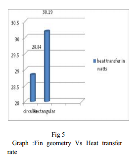
Referring to fig.5 it is seen that the rate of heat transfer through the condenser is maximum for the rectangular fin geometry when compared to the circular fin geometry of the condenser. In the existing system condenser fin geometry is circular. When compared with the rectangular fin geometry of the condenser the present work produces the following results. Heat transfer rate is increased by 4.68% For the rectangular fin geometry when compared to the circular fin geometry. This is because of rectangular plate fins have more surface area. The Refrigerator condenser performance can be enhanced with the help of Rectangular plate fin geometry of the condenser
Where
?Tm = log mean temperature difference. Condenser entering temperature = 56.2 0 C Condenser leaving temperature = 45.8 0 C Air temperature at the condenser inlet = 33.2 0 C Air temperature at the condenser outlet = 34.20 C
Analysis of the condenser: Thermal analysis in the heat exchangers can be done in two ways. 1. LMTD Method (Logarithmic Mean Temperature Difference) 2. NTU Method ( Number of Heat transfer Units) LMTD Method is useful when the inlet and outlet fluid temperatures of condenser and air are known. NTU Method is useful when the heat exchanger is designed for the particular mass flow rate. For the given conditions LMTD Method is suitable. LMTD Method: In a heat exchanger, the temperature of the heating and cooling fluids do not in general, remain constant, but vary from point to point along the length of the heat exchanger. Since the temperature difference between the two fluids keeps changing, the rate of heat transfer also changes along the length of the heat exchanger as shown.
The rate of heat transfer can be calculated from the relation Q = U A ?T Since ?T changes from point to point in a heat exchanger, we propose to use ?Tm, a suitable mean temperature difference
Properties of R-134(a) are taken at bulk mean temperature of condenser with different fin geometry. Bulk mean temperature of condenser can be calculated by = (Condenser inlet temp. + Condenser outlet temp.)/2 In order to calculate convective heat transfer coefficient of R-134(a) the following steps are to be followed and the convection is of forced convection pipe flow with respect to refrigerant.
n = 0.4 for heating of the fluid and 0.3 for cooling of the fluid The Dittus-Boelter equation is valid for 0.7< Pr 10000 The Dittus-Boelter equation is good approximation where temperature differences between bulk fluid and heat transfer surface are minimal.
Nusselt number: In heat transfer at boundary (surface) within a fluid, the Nusselt number is the ratio of convective to conductive heat transfer across (normal to) boundary. Named after Wilhelm Nusselt, it is a dimensionless number. A Nusselt number is close to one for slug or laminar flow. It varies for turbulent flow. For forced convection, the Nusselt number is generally a function of the Reynolds number and prandtl number, or Nu = f (Re, Pr). Calculation of overall heat transfer coefficient Condenser coil dimensions: Outer diameter of tube = 6.5mm Inner diameter of tube = 6mm
RESULTS AND CONCLUSIONS
Referring to fig.5 it is seen that the rate of heat transfer through the condenser is maximum for the rectangular fin geometry when compared to the circular fin geometry of the condenser. In the existing system condenser fin geometry is circular. When compared with the rectangular fin geometry of the condenser the present work produces the following results. Heat transfer rate is increased by 4.68% For the rectangular fin geometry when compared to the circular fin geometry. This is because of rectangular plate fins have more surface area. The Refrigerator condenser performance can be enhanced with the help of Rectangular plate fin geometry of the condenser.
References:
1. Abu Madi M. Johns, R.A and Heikal M.R (1998).Performance chracteristics correlation for round tube and plate finned heat exchangers, int J.Refrigeration.Vol.21(7),pp.507-517.
2. Achaichia,A and Cowel ,T.A (1998).Heat transfer and pressure drop characteristics of flat tube and louvered plate fin surfaces ,Exp .Thermal fluid sci.Vol 1(2),pp.147-157.
3. Chang,W.R Wang C.C Tsi W.c and Shyu, R.J(1995)Air side performance of louver fin heat exchanger,4 th ASME/JSME Thermal Engineering Joint Conference.Vol.4,pp.467-372.
4. Du, Y.J and Wang CC (2000).An Experimental study of the Airside performance of the superslit Fin-andTube Heat exchangers.Int.J.Heat mass transfer,Vol.43,pp.4475-4482
5. Gray.D.L and Webb, R.L(198^)Heat Transfer and Frictio Correlations for plate Finned-Tube Heat Exchangers having plain fins ,proceeding 8 th International journal of Heat transfer conference,Vol.6,pp.2745-2750
|
 IJCRR
IJCRR 


 This work is licensed under a Creative Commons Attribution-NonCommercial 4.0 International License