IJCRR - 4(12), June, 2012
Pages: 125-131
Date of Publication: 22-Jun-2012
Print Article
Download XML Download PDF
THERMAL ANALYSIS OF EXHAUST WASTE HEAT FOR COOLING USING NH3-H2O ABSORPTION REFRIGERATION SYSTEM
Author: Om Prakash, Ritesh Kumar Chaurasiya
Category: Technology
Abstract:This research paper includes the detailed thermodynamic analysis of waste heat from DG set system and power plants and also the analysis of NH3-H2O vapour absorption refrigeration system. This work proposes the direct utilization of waste heat to power absorption refrigeration system. This analysis includes heoretical calculation of heat required for generator, refrigerating effect produced and equired mass flow rate of refrigerant for the typical power generating unit. This research shows that considerable amount of cooling effect and energy saving would result from direct utilization of the exhaust waste heat of DG set system or power plants which will reduces the losses of energy, therefore reduces the emission of green house effect gasses..
Keywords: Waste heat, Vapour absorption refrigeration system (VARS), Circulation ratio
Full Text:
INTRODUCTION
Most of industrial process uses a lot of thermal energy by burning fossil fuel to produce steam or heat. After the processes, heat is rejected to the surrounding as waste. This waste heat can be converted to useful refrigeration by using a heat operated refrigeration system, such as an absorption refrigeration cycle 1 . Despite a lower coefficient of performance (COP) as compared to the vapor compression cycle, absorption refrigeration systems are promising by using inexpensive waste energy from industrial processes, geothermal energy, solar energy etc 2 . The absorption refrigeration system is heatoperated unit, which uses a refrigerant that is alternately absorbed by and liberated from the absorbent. Absorption units operate on the simple principle that under low absolute pressure, water will boil at a low temperature. The two-shell cooling units use heat to produce refrigeration efficiently. The lower shell contains an absorber and evaporator, while the upper shell consists of generator and condenser sections 3 . A survey of absorption fluids suggested that, there are some 40 refrigerant compounds and 200 absorbent compounds available 4 . However, the most common working fluids are NH3-H2O and LiBr-H2O. It is reported that LiBr-H2O has a higher COP than for the other working fluids though it has a limited range of operation due to the onset of crystallization occurring at the point of the recuperator discharge into the absorber and stopping solution flows through the device 5 . In this research work vapour absorption refrigeration systems based on ammonia-water (NH3-H2O) pair has been considered in which ammonia is the refrigerant and water is the absorbent. These systems are more versatile than systems based on water-lithium bromide as they can be used for both sub-zero (refrigeration) as well above 0 oC (air conditioning) applications. The NH3-H2O system requires generator temperatures in the range of 125°C to 170°C with air-cooled absorber and condenser and 80°C to 120°C when water-cooling is used. The coefficient of performance (COP), which is defined as the ratio of the cooling effect to the heat input, is varies from 0.6 to 0.7 6 . This research includes thermodynamic analysis of waste heat from power generating units and NH3-H2O vapour absorption refrigeration system. The unique feature of present work is that the direct utilization of waste heat to power in the NH3-H2O absorption refrigeration system will reduces the losses of energy resulting in reducing pollution.
MATERIALS AND METHODS
Waste heat energy sources For the analysis of cooling effect produced by waste energy, three systems are considered including:
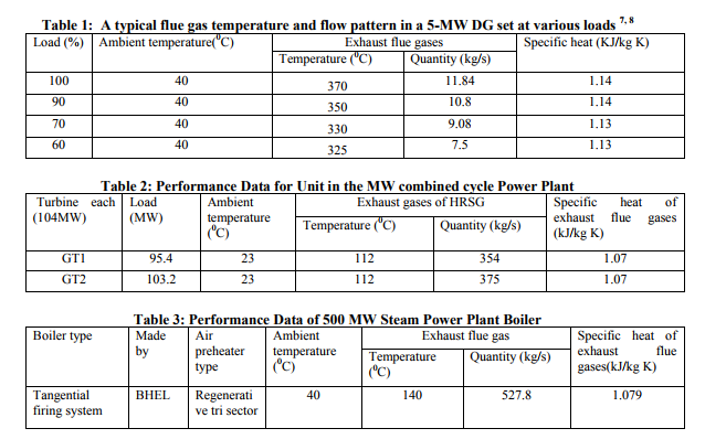
1. A typical DG set system of 5 MW operating at different loads. The details are given in the table 1.
2. The combined cycle gas turbine power plant in Pragati Power Corporation Ltd., Delhi. It consists of 2 x 10⁴ MW Frame 9-E Gas turbine and 1x122MW steam turbine. These turbines, namely gas turbine#1 (GT1) and gas turbine #2 (GT2) are selected for the present analysis. Performance data of gas turbines are given in table 2.
3. 500 MW steam power plant installed in MTPS-DVC, Bankura, in which the waste heat from the boiler exhaust is utilized. The performance data of boiler is given in table 3.
Cooling System
NH3- H2O Vapour absorption chiller specifications:
Average Generator temperature = 100 0C.
Average Condenser temperature = 46 0C.
Average Absorber temperature = 40 0C.
Average Chilled-water temperature= 7 0C. COP of the system= 0.6.
Calculation of heat energy
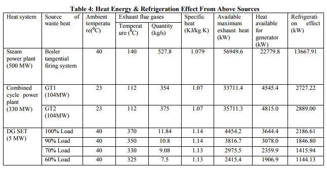
Available maximum exhaust heat, heat available for generator and refrigeration effect from above sources are calculating as per the relation given in table 4. Available maximum exhaust heat = mex.Cp,ex.(Tex - Ta) kW Heat available for generator (Qg) = mex.Cp,ex.(Tex - Tg) kW Refrigeration effect (Qe) = COP * Qg kW
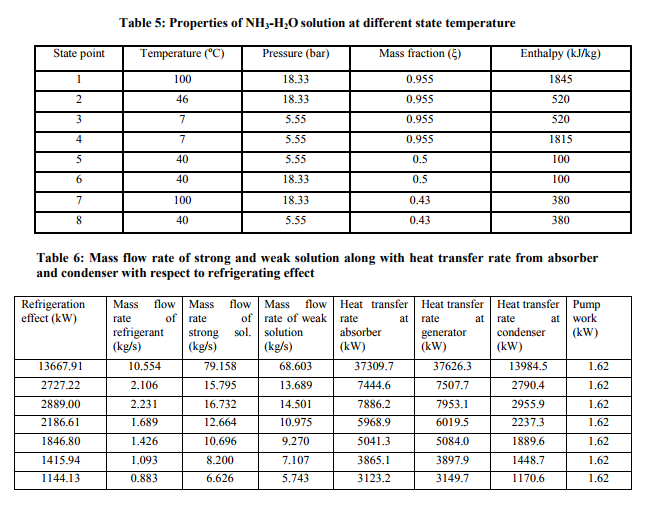
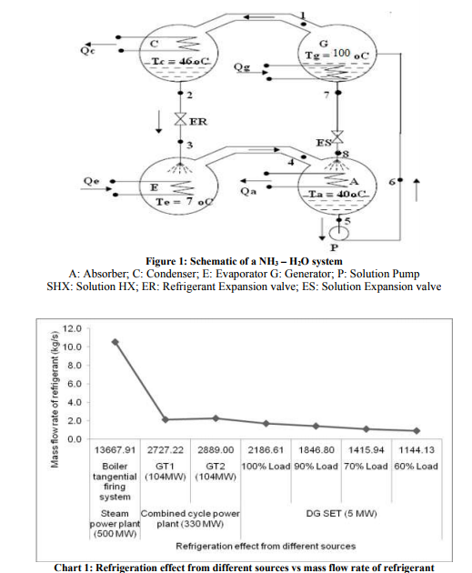
Thermal analysis of NH3-H2O vapour absorption refrigeration system using available exhaust heat Assuming pure ammonia vapours are evolved in generator, we have for pressures from the table of properties of ammonia 9 . Pc = Psat (Tc) Pe = Psat(Te) Strong solution concentration of NH3 from enthalpy-composition diagram for NH3 – H2O system ξss [sat. liquid at absorber temperature (Ta) & pressure (Pa)] Weak solution concentration of NH3 from enthalpy-composition diagram for NH3 – H2O system ξws [sat. liquid at generator temperature (Tg) & pressure (Pg)] The concentration of NH3 in vapour leaving generator ξv [sat. vapour at generator temperature (Tg) & pressure (Pg)] The properties of NH3-H2O solution at different temperature state ( Figure 1) are given with the help of enthalpy-composition diagram for NH3 – H2O system, and given in table 5.
Now specific strong solution circulation rate λ = (ξv – ξws)/ (ξss – ξws) Specific weak solution circulation rate λ -1 Mass flow rate Required mass flow rate of refrigerant, mr = Qe / (h4-h3) (1) mass flow rate of strong solution, mSS = λmr (2) mass flow rate of weak solution, mWS = (λ-1)mr (3) Heat transfer rates at various components
Evaporator Qe
Absorber
From energy balance: Qa = mrh4 + mwsh8 – mssh5 (4)
Generator
From energy balance Qg = mrh1 + mwsh7– mssh6 (5) Condenser From energy balance Qc = mr (h1-h2) (6)
Solution pump work
(assuming the solution to be incompressible) WP = vsol(P6-P5) = (P6-P5)/ρsol (7) Where m = Mass (kg) Cp = Specific heat (kJ/kg K) COP = Coefficient of performance P = Pressure (kPa) T = Temperature (0C) ξ = Mass fraction λ = Circulation ratio Q = Heat energy (kW) h = Specific enthalpy (kJ/kg) W = Work (kJ) v = Specific volume (m3 /kg) ρ = Density of the flue gas kg/m3 Subscripts ex exhaust flue gas a absorber g generator e evaporator c condenser r refrigerant ss strong solution ws weak solution sat saturation state p pump sol solution hx heat exchanger v superheated water vapour The theoretical calculated values of mass flow rate of refrigerant, strong and weak solution along with heat transfer rate at various components with respect to refrigerating effect for this analysis are given in table 6 and mass flow rate of refrigerant required for calculated values of refrigerating effect from different available waste heat sources are also shows in chart 1.
RESULTS
The purpose of the present research was to analyze the methods and means of utilizing the waste heat of power generating units for driving an absorption refrigeration system. The following results are calculated from the research work: ? In the steam power plant (500 MW), the waste heat analysis applied to boiler (MTPSDVC Bankura) could produce cooling effect up to 13667.91 kW. ? In the combined cycle power plant of 330 MW, waste heat analysis applied to GT1 & GT2 of (PPP-Delhi), produces the cooling effect up to 2727.22 & 2889 kW respectively. ? In the DG set system of 5 MW, waste heat analysis at 100%, 90%, 70% & 60% load, produces the cooling effect up to 2186.61, 1846.8, 1415.94 &1144.13 kW respectively
DISCUSSION
The present research work concluded that direct utilization of waste heat to heat solution in generator and the operation of an absorption refrigeration system on that hot exhaust flue gas could be a successful approach. The theoretical analysis for both the power generating units and the NH3-H2O vapour absorption refrigeration system showed that the suggested inexpensive heat recovery load would be in the form of hot flue gases will be in the operating range of the absorption refrigeration cycle. It is recommended that the utilization of rectification column and dephlegmator in NH3- H2O absorption refrigeration system could improve the performance of the system.
ACKNOWLEDGEMENT
Authors acknowledge the immense help received from the scholars whose articles are cited and included in references of this manuscript. The authors are also grateful to authors / editors / publishers of all those articles, journals and books from where the literature for this article has been reviewed and discussed.
References:
1. Srikhirin P, Aphornratana S and Chungpaibulpatan S, A review of absorption refrigeration technologies. Renewable and Sustainable Energy Review. Elsevier 2001 Dec; 5 (4): 343-372.
2. Crepinsek Z, Goricanec D and Krope J., Comparison of the Performances of working fluids for absorption refrigeration systems.WSEAS transactions on heat and mass transfer, WSEAS 2009 July; 4 (3) 65- 76.
3. A. EI Masry Osama, Performance of waste heat absorption refrigeration system. The 6th Saudi Engineering Conference; December 14- 17, 2002; KFUPM, Dhahran; 2002. p. 531-545.
4. Marcriss R.A, Gutraj J.M and Zawacki T.S. Absorption fluid data survey: final report on worldwide data: Dept. of Energy (US). Prepared by Institute of Gas Technology. Virginia: National Technology Information Service;1988. Contract No.: DEAC05840R21400.
5. Li Z. F and Sumathy K, Technology development in the solar absorption airconditioning systems. Renewable and Sustainable Energy Reviews. Elsevier 2000 Sept; 4 (3): 267-293.
6. Kalogirou S. Recent Patents in Absorption Cooling Systems, Recent Patents on Mechanical Engineering 2008; 1(1); 58-64.
7. Bureau of Energy Efficiency. BEE Exam Guidebooks, Chapter 9- DG Set System, pp 165-178.
8. Kothandaraman C. P. and Subramanyan S. Heat And Mass Transfer Data Book. Property Values. 6th ed. New Delhi: New Age International Publishers; 2007. P.1-38.
9. Arora, C. P. Refrigeration and air conditioning. Vapour-Absorption System. 2 nd ed. New Delhi: Tata McGraw – Hill; 2006. p. 427-65.
|
 IJCRR
IJCRR 


 This work is licensed under a Creative Commons Attribution-NonCommercial 4.0 International License