IJCRR - 4(14), July, 2012
Pages: 148-154
Date of Publication: 31-Jul-2012
Print Article
Download XML Download PDF
DESIGN OF A ULTRA WIDE-BAND CAPACITIVE FEED MICROSTRIP PATCH ANTENNA FOR Ku-BAND
APPLICATIONS
Author: M. Sowmya, M. Venkata Narayana, I. Govardhani, Habibulla Khan
Category: General Sciences
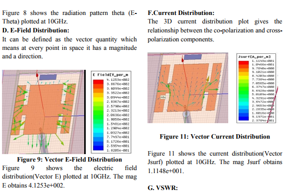
Abstract:A ultra wideband micro-strip patch antenna with capacitive feed is presented here. In recent years microstrip patch antennas are widely used in communication systems because of their characteristics such as low cost, low profile structure and minimal weight. Due to these characteristics, micro-strip antennas are capable of maintaining high performance over a wide spectrum of frequencies, also the size of the antenna is directly tied to the wavelength at the resonant frequency. One of the important aspects in micro-strip patch antenna is the feed applying to them. Since, the performance of the basic micro-strip patch antenna suffers from number of serious drawbacks; especially its narrow impedance bandwidth associated with probe-fed micro-strip antennas. Here, a capacitive feeding scheme is used which comprises of a radiator patch, air cavity in the substrate and a capacitively-fed in order to overcome the drawbacks associated with probe-fed. Slots are used in the radiating patch at the four sides to attain improved bandwidth. Different parameters like return loss, gain(both 2D & 3D),VSWR, radiation patterns, E & H fields, current distribution are simulated using Ansoft HFSS 13.0. This type of proposed patch can be used for various applications in Ku-band.
Keywords: Micro-strip antenna, capacitive feed, air cavity.
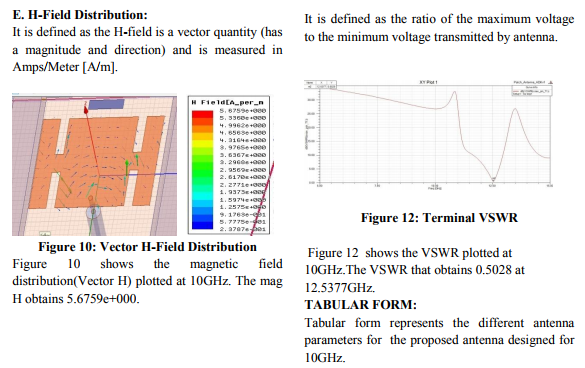
Full Text:
INTRODUCTION
In high-performance aircraft, spacecraft, satellite and missile applications, we have small size, less weight, low cost, high performance, ease of installation, and aerodynamic profiles are constraints, so we require low profile antennas. Presently there are many other government and commercial applications, such as mobile radio and wireless communications that have similar specifications. To meet these requirements, Microstrip antennas can be used. These micro-strip antennas are low profile, conformable to planar and non planar surface, simple and inexpensive to manufacture using modern printed circuit technology, mechanically robust when mounted on rigid surfaces, and when the particular patch shape and mode are selected; they are very versatile in terms of resonant frequency, polarization, pattern and impedance. In addition by adding the load between patch and ground plane such as pins, adaptive elements with variable resonant frequency, impedance, polarization and pattern canbe designed. In the contacting method, the RF power is fed directly to the radiating patch using a connecting element such as a micro-strip line. In the noncontacting scheme, electromagnetic field coupling is done to transfer power between the micro-strip line and the radiating patch. The Coaxial feed or probe feed (contacting method) is a very common technique for exciting a micro-strip patch antenna. Probe feeding is also referred to as a direct contact excitation mechanism. However, the electrical performance of the basic probe-fed micro-strip antenna suffers from a number of serious drawbacks, especially its narrow impedance bandwidth restricts the performance of antennas in UWB applications [1]. The basic reason for narrow impedance bandwidth is the high quality factor of micro-strip antenna, so decreasing the quality factor is an effective way to increase antenna's impedance bandwidth. One way for decreasing the quality factor is to increase the thickness of the substrate. However, increasing the thickness of the substrate leads to the surface wave excitations i.e., the total power delivered by source goes into surface wave. This surface wave causes the degradation of antenna characteristics. Therefore, antenna technologies about bandwidth enhancement and size reduction are becoming the major design considerations for practical applications. This kind of bandwidth-enhancement technique includes:
- the use of a thick air or foam substrate
- the loading of a chip resistor or matched network
- the changing of antenna shape.
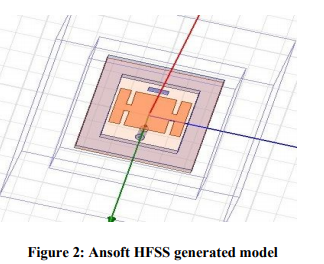
To overcome this problem associated with probefed micro-strip antennas, several useful techniques applied to improve the bandwidth and size reduction. One of the technique is adding a capacitive component to the input impedance of the radiating patch, which compensates for the inductive component of the feed by embedding a cutting slots in it[3]. In this paper, a new ultra-wide bandwidth antenna excited by a capacitively-fed patch with air cavity is proposed. The bigger patch acts as radiator patch, while the smaller patch placed very close to it acts as feed strip. Coaxial feeding is used to excite feed strip has used which is compatible with air gap below the substrate. Very small slots are used at 4 sides of the radiating patch. These slots can be used to increase the total surface current length there by we can improve the radiation. Entire geometry of the antenna is easy to design which makes the structure of the patch symmetrical. Results are simulated using Ansoft HFSS 13.0.
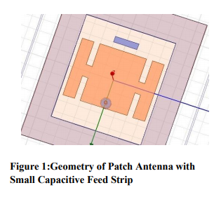
ANTENNA DESIGN MODEL:
In order to improve the antenna's impedance bandwidth and reduce the weight of antenna, an air square cavity is made as part of substrate. Figure 1 shows the basic structure of the proposed antenna with the larger patch served as the radiator and the smaller one worked as a feed strip which couples the energy to the radiator by capacitive means. The antenna substrate is placed above the ground plane and below the radiator patch with a air cavity. The substrate material used for the antenna is Rogers RT/ Duroid 5880 with dielectric constant εr of 2.2 with length of 2.7cm and width of 2.3cm. The main radiator patch element is placed on the air cavity with length 1cm and width 1.4cm.The smaller patch called feed strip is placed very close to the radiator patch with length of 0.1cm and width of 0.4cm.Coaxial probe feed is applied to the radiator patch which increases the gain of the antenna. However, if the probe feed is given to the feed strip element the gain of the antenna decreases. The air cavity is located in the centre of substrate. The length of the air cavity is 1.8cm and width is 1.53cm.The thickness of the air cavity is considered to be same as the thickness of the substrate material. The air cavity is cutted and placed at the center of the substrate.
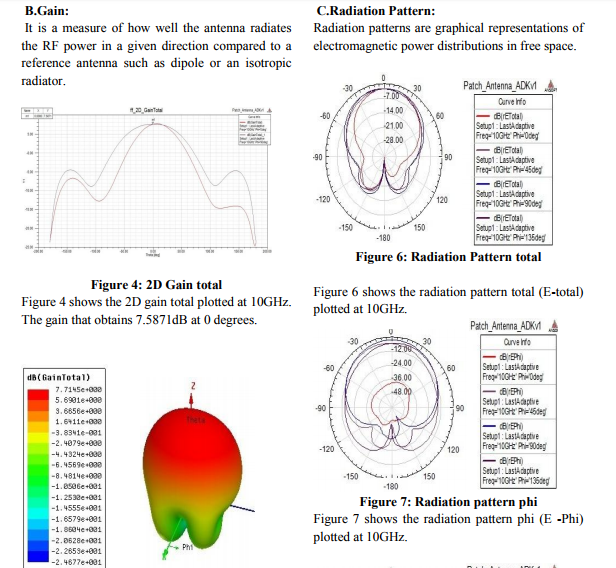
maximizing the bandwidth. Here, first the gain is measured for the same dimensions of the radiator patch, feed strip elements without air cavity.The gain obtained for this structure without air cavity is around 3dB. But,the gain obtained for the same structure with same dimensions is about 7.714dB. It is certainly understood that, the air cavity locates in the substrate and as the effective substrate height increases or permittivity decreases, the bandwidth of the antenna becomes wider. For maximizing the bandwidth the air gap should be such that[3]: (1) Where is the wavelength corresponding to the frequency of the operating band, h is the height of the substrate and is the relative dielectric constant of the substrate. However, the air cavity in the designed antenna is fully surrounded by substrate,so we need to amend the formula as[3]: (2) Not only the effect of air cavity for the proposed antenna, also the dimensions and location of the feed strip play a major role in obtaining the wide bandwidth. Based on all these simulations are done using Ansoft HFSS 13.0 which is a FEM(Finite Element Method) based, electromagnetic(EM) simulation software.
SIMULATION RESULTS
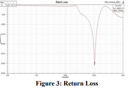
A. Return Loss: It is related to impedance matching and the maximum transfer of power theory. It is also a measure of the effectiveness of an antenna to deliver of power from source to antenna
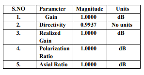
TABULAR FORM:
Tabular form represents the different antenna parameters for the proposed antenna designed for 10GHz.
CONCLUSION
A ultra wideband micro-strip patch antenna with small capacitive feed is proposed & designed for the wideband operation in the Ku-band. The effect of air cavity placed at the center of the substrate(Rogers RT/Duroid 5880)plays a critical role in increasing the gain and other parameters of the antenna. And also the slotted sided patch proposed here is mainly to get the constant radiation pattern. The main purpose of using the slots in th patch is for balancing the resistive part & reactive part which affect the impedance matching. In this design, the proposed antenna can operate at 10GHz with return loss (S11) <10dB &the proposed antenna displays a good radiation pattern even at the higher frequencies. Good return loss (S11), VSWR, bandwidth & radiation pattern characteristics are obtained in the frequency band of interest. The performance properties are analyzed for the optimized dimensions and the proposed antenna works well for the Ku-band applications.
ACKNOWLEDGEMENT
The authors like to express their thanks to the department of ECE and the management of K.L.University, Vijayawada for their excellent support and encouragement during the tenure of work.
References:
1. L 1. Bahl and P. Bhartia , Micro-strip Antenna, Norwood, MA: Artech House, 1980.
2. Wong, K. L., Compact Broadband Micro-strip Antenna, John Wiley & Sons, New York, 2002.
3. Liu Ying, Liu Jianping, Li Ping, Designing a Novel Broadband Micro-strip Antenna with Capacitive Feed, IEEE Cross Strait QuadRegional Radio Science and Wireless Technology Conference(CSQRWC),Vol. 1,pp. 156-159,july 2011.
4. P.S.Nakar.,‘Design of a Compact Microstrip Patch Antenna‘,John Wiley & sons,Newyork,2002.
5. Piyush Musale,Sanjay V.Khobragade, Capacitive Feed for Slotted Micro-strip Antenna, IEEE General Assembly & Scientific Symposium,Aug 2011.
6. C. A. Balanis, Antenna Theory Analysis and Design, Second Edition, New York, Wiley, 1997.
7. Veeresh G. Kasabegoudar, Dibyant S. Upadhyyay, and K. J. Vinoy. Design studies of ultra wide band micro-strip antennas with a small capacitive feed. International Journal of Antennas and Propagation, voL 2007, Article ID 67503, 8 pages, 2007. doi:10. 115512007/67503.
8. G. Mayhew-Ridgers, l.W. Odondaal and 1. Joubert, Single-layer capacitive feed for wide band probe-fed microstrip antenna elements, IEEE Trans. Antennas Propagation, voL 5 1, pp. 1405-1407, Nov. 2003
9. J. Constantine, New Multi Band Design for a Microstrip Patch Antenna Masters thesis, American University of Beirut, October 2006.
10. 1. G. Kumar and K. P. Ray, Broadband Microstrip Antennas, Artech House, Norwood, Mass, USA, 2003.
11. Mukesh R. Solanki, Usha Kiran K., and K. J. Vinoy,? Broadband Design of a Triangular Micro-strip Antenna with a Small Capacitive Feed? Journal of Microwaves,Optoelectronics and Electromagnetic Applications, Vol. 7,No.1, June 2008.
12. Lee Chia Ping Chakrabarty, C.K. Khan, R.A. ?design of Ultra Wideband slotted micro-strip patch antenna?, Dept . of Electron. & Communication Eng., Centre for Communication Service Convergence Technol., Kajang, Malaysia Electronics Letters, vol. 40, no. 19, pp. 1166–1167, 2004.
13. N. Herscovici, ?New considerations in the design of microstrip antennas.? IEEE Transactions on Antennas and Propagation, AP- 46, 6, June 1998, pp. 807-812.
14. Sanad, M. ?Microstrip Antennas on Very Small Ground Planes for Portable Communication Systems?. Proceedings of the IEEE Antennas and Propagation Society Symposium, June 1994, pp. 810-813.
|
 IJCRR
IJCRR 


 This work is licensed under a Creative Commons Attribution-NonCommercial 4.0 International License