IJCRR - 4(22), November, 2012
Pages: 180-184
Date of Publication: 24-Nov-2012
Print Article
Download XML Download PDF
BAND WIDTH ENHANCEMENT OF RECTANGULAR MICROSTRIP PATCH ANTENNA BY INCREASING SUBSTRATE HEIGHT FOR C- BAND ADVANCE WIRELESS COMMUNICATION SYSTEMS
Author: Sarman Kumar Ahirwar, Jayprakash Updhyay
Category: Technology
Abstract:A wideband rectangular patch antenna [1] is designed for wireless local area network (WLANs) applications. These antennas operate for 4-7 GHz ISM band, and wideband applications. The antenna has the dimensions of 20 mm by 15 mm by 1.8 mm on FR4 substrate with dielectric constant 4.4. The substrate height is increased in each antenna to enhance the bandwidth. All dimensions are same in each antenna. The antenna is simulated by Ansoft Higher Frequency Structure Simulator (HFSS) software which is finite element method based simulator. After simulation the antenna performance characteristics such as, input impedance, return loss, Impedance band width, percentage bandwidth and polar plot are obtained.
Keywords: Wideband antenna, WLANs, ISM band, microstrip patch antenna.
Full Text:
INTRODUCTION
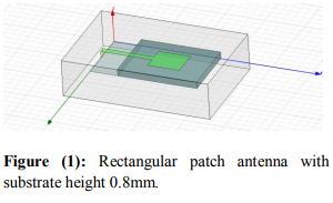
The future generation wireless networks require systems with broad-band capabilities in high mobility environments [2], to satisfy several applications as personal communications, home, car, and office networking. The wireless communication market has been greatly expanded and the demands of Industrial, Scientific, and Medical (ISM) band are increasing [3]. The current fastest and robust WLANs operate in the 5–6 GHz band (e.g., IEEE 802.11)[4] which can provide reliable high-speed connectivity between notebook computers, PCs, personal organizers and other wireless digital appliances. The proposed antenna can operate from 4.12 to 5.68 GHz making it suitable for wideband applications. The frequency band of this antenna covers the entire 5.15-5.825 GHz ISM band [5][6]. This small printed monopole antenna can be used in the biomedical engineering domain, and to be mounted on the medical devices. In the last decades printed antennas have been largely studied due to their advantages over other radiating systems, which include: light weight, reduced size, low cost, conformability and the ease of integration with active device. A Microstrip Patch antenna consists of a radiating patch on one side of dielectric substrate which has a ground plane on the other side as Shown in Figure 1. The patch is generally made of conducting material such as copper or gold. The radiating patch and the feed lines are usually photo etched on the dielectric substrate. Microstrip patch antennas radiate primarily because of the fringing fields between the patch edge and the ground plane. Therefore, the antenna can be fed by a variety of methods. These methods can be Classified into two categories- contacting and non-contacting. In the contacting method, the RF power is fed directly to the radiating patch using a connecting element such as a microstrip line or probe feed. In the non-contacting scheme, electromagnetic field coupling is done to transfer power between the microstrip line and the radiating patch this includes proximity feeding and aperture feeding [7].
RESEARCH METHODOLOGY
In my research, it is shown that the substrate height can be increased to enhance the bandwidth.
Antenna Design and Simulated Results
A. Geometry of Antenna
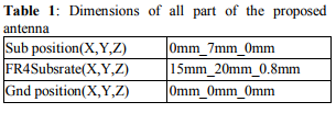
The structure of the proposed antenna is shown in Figure 1. For a rectangular patch, the length L of the patch is usually 0.333 λ0< L < 0.5 λ0, where λ0 is the free-space wave length. The patch is selected to be very thin such that t << λ0 (where t is the patch thickness).The height h of the dielectric substrate is usually 0.003 λ0 < h < 0.05 λ0 [7][8]. The geometry of the proposed antenna is showed in Fig.1. It consists of a printed rectangular patch antenna on FR4 substrate of thickness 1.8 mm and a relative permittivity 4.4. The substrate has a length of L=20 mm and the width of W=15 mm. The dimensions of the partial conducting ground plane are 15mm×7 mm. The patch dimension are L=7mm and W=8mm.The excitation is launched through a 50 Ohm microstrip feed line, which has the length 8mm and the width 1.5mm.
In this paper, The substrate height have been increased for bandwidth improvement[10], in order to cover the entire 5-6GHz band, and make the antenna suitable for 5 to 6 GHz applications[11].
B. Criteria Design
For the first case, the antenna operates from 4.46to 5.26 GHz, This bandwidth covers the lower part of the UWB as defined by FCC [13]. In the Second case, increase the substrate heights to widen the operational bandwidth by enhancing upper frequency and lower frequency. The antenna operates from 4.12 to 5.68 GHz. the patch antenna allows to shift the frequency band in the direction of the higher frequencies and lower frequency. This enhances the lower and the upper frequency, thus the antenna covers well the entire 5-6GHz band. In the third case, antenna operates from 3.81 to 7GHz frequency band. And bandwidth increase with the substrate height.
C. Simulation Setup
The software used to model and simulate the microstrip patch antenna is HFSS software [9]. HFSS software is a full-wave electromagnetic simulator based on the finite element method. It analyzes 3D and multilayer structures of general shapes. It has been widely used in the design of MICs, RFICs, patch antennas, wire antennas, and other RF/wireless antennas. It can be used to calculate and plot the S parameters, VSWR, current distributions as well as the radiation patterns.
D. Results:
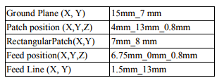
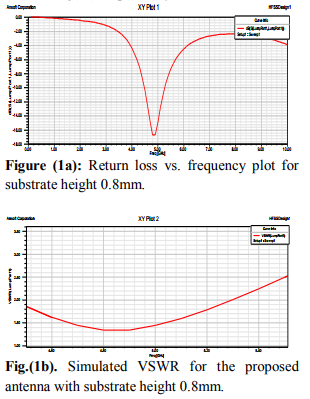
Return loss is important parameter for calculating the bandwidth of the antenna. The center frequency is selected as the one at which the return loss is minimum. The bandwidth can be calculated from the return loss (RL) plot. The bandwidth of the antenna can be said to be those range of frequencies over which the RL is greater than -10 dB (-10 dB corresponds to a VSWR of 1.34 which is an acceptable figure). In the first case, when the substrate height is taken 0.8mm, then the impedance bandwidth is obtained 0.8052GHz and the percentage bandwidth is 8.36% with center frequency of 4.8 GHz. Antenna return loss is -16.68 and VSWR is 1.5. The return loss and VSWR are shown in fig (1a) and fig(1b) respectively.
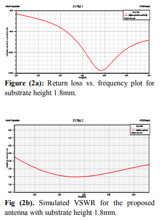
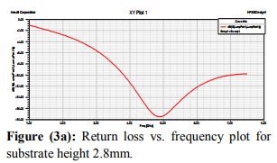
In the second case, when the substrate height is increased from 0.8mm to 1.8mm then the impedance band width is increased to 1.566GHz and percentage band width is obtained 16.30% with centre frequency 4.8GZz. The return loss is obtained -13.72 and VSWR 1.5. The return loss and VSWR is shown in fig(2a) and fig(2b) respectively.
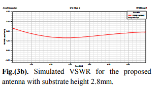
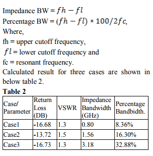
In the third case, when the substrate height is increased from 1.8mm to 2.8mm then the impedance band width is increased to 3.18GHz and percentage band width is obtained 32.88% with centre frequency 4.8GZz. The return loss is obtained -16.73 and VSWR 1.34. The return loss and VSWR is shown in fig(3a) and fig(3b) respectively.
The simulated result of my design are shown in the following table. The impedance bandwidth and percentage bandwidth are calculated by following formulas.
DISCUSSION
Thus it very easy process to improve the bandwidth and is important where antenna size is not important.
CONCLUSION
It is shown that the simulations results obtained by HFSS simulator show good agreement. The proposed rectangular patch antenna can be good candidate for 5 to 7 GHz applications and wideband applications, due to its miniature size, and its good performances [12-14]. It is shows that how the bandwidth is increased with substrate height.
ACKNOWLEDGEMENT
The authors of this paper would like to thank Prof. Sunil kumar singh, Jabalpur Engineering College Jabalpur M.P. India helping us to carry out the HFSS simulations.
References:
1. M. Ali, T. Sittironnarit, H.S. Hwang, R. A. Sadler,and G. J. Hayes, “Wide-Band/DualBand Packaged Antenna for 5–6 GHz WLAN Application,”IEEE Trans. Antennas Propagat.,vol.52, N.2. pp. 610-615, February. 2004.
2. J. L. Pan, S. S. Rappaport, and P. M. Djuric, “Amultibeam medium access scheme for multiple services in wireless cellular communications,” in Proc. IEEE 1999 Int. Conf. Communication, vol.3, 1999, pp. 1673–1677.
3. L. Jofre, B. A. Cetiner, and F. Flaviis, “Miniature Multi-Element Antenna for Wireless Communications,” IEEE Trans. Antennas Propagat., vol.50, N. 5. pp. 658– 669, May 2002.
4. I-F. Chen, C. M. Peng, and S-C. Liang, “Single Layer Printed Monopole Antenna for Dual ISMBand Operation,” IEEE Trans. 1273, April.2005.
5. R. Jordan and C.T. Abdallah, “Wireless communications and networking: An overview,” IEEE Antennas Propag. Mag., vol. 44,pp.185–193, Feb. 2002.
6. Availablein:http://standards.ieee.org/catalog/ olis/lanman.html.
7. A. Balanis, “Antenna Theory analysis and design”, Microstrip Antenna, Chapter 14, pp.720-784
8. Pozar D.M., and Schaubert D.H (1995) Microstrip Antennas, the Analysis and Design of Microstrip Antennas and Arrays, IEEE Press, New York, USA
9. Ansoft High Frequency Structure Simulatorcorporation, V 9.2, 2004, http://www.ansoft.com/hfss
10. Ramesh G, Prakash B, Inder B, and Ittipiboon A. (2001) Microstrip antenna design handbook, Artech House.
11. Zeadally, S. and L. Zhang, “Enabling gigabit network access to end users,” Proc. IEEE, Vol. 92, No. 2, 340–353, 2004.
12. Tsai, M. J., F. D. Flaviis, O. Fordham, and N. G. Alexopoulos, “Modeling planar arbitrarily shaped microstrip elements in multilayered media,” IEEE Trans. Microwave Theory Tech.,Vol. 45, 330–337, 1997.
13. Sharma, A. and G. Singh, “Design of single pin shorted three dielectric layered substrate rectangular patch microstrip antenna communication systems,” Progress In Electromagnetics Research Lett., Vol. 2, 157–165, 2008.
14. Waterhouse, R. B., S. D. Targonski, and D. M. Kokoto, “Design and performance of small printed antennas,” IEEE Trans. Ant. Prop., Vol. 46, 1629–1633, 1998
|
 IJCRR
IJCRR 


 This work is licensed under a Creative Commons Attribution-NonCommercial 4.0 International License